Eureka AIR delivers breakthrough ideas for toughest innovation challenges, trusted by R&D personnel around the world.

Thin-film magnetic head and method of manufacturing same, head gimbal assembly, and hard disk drive

A technology of a thin film magnetic head and a manufacturing method, which is applied to a magnetic head using a thin film, a magnetic recording head, a magnetic flux sensitive magnetic head, etc., can solve the problem that it is difficult to reduce the deviation of the magnetic pole width, and it is difficult to form a photoresist with high precision. borders etc.

Inactive Publication Date: 2008-04-09
TDK CORPARATION
View PDF9 Cites 0 Cited by
  • Summary
  • Abstract
  • Description
  • Claims
  • Application Information

AI Technical Summary

Problems solved by technology

However, in this technique, a photoresist frame is formed not on a flat surface but on a surface where a step is created by an insulating layer defining a front height.
Therefore, it is difficult to form a photoresist frame with high precision
Therefore, in this technique, in particular, when reducing the magnetic pole width below 0.3 µm, there is a problem that it is difficult to reduce the deviation of the magnetic pole width.

Method used


Image

  • Thin-film magnetic head and method of manufacturing same, head gimbal assembly, and hard disk drive
  • Thin-film magnetic head and method of manufacturing same, head gimbal assembly, and hard disk drive
  • Thin-film magnetic head and method of manufacturing same, head gimbal assembly, and hard disk drive

Examples


Embodiment Construction

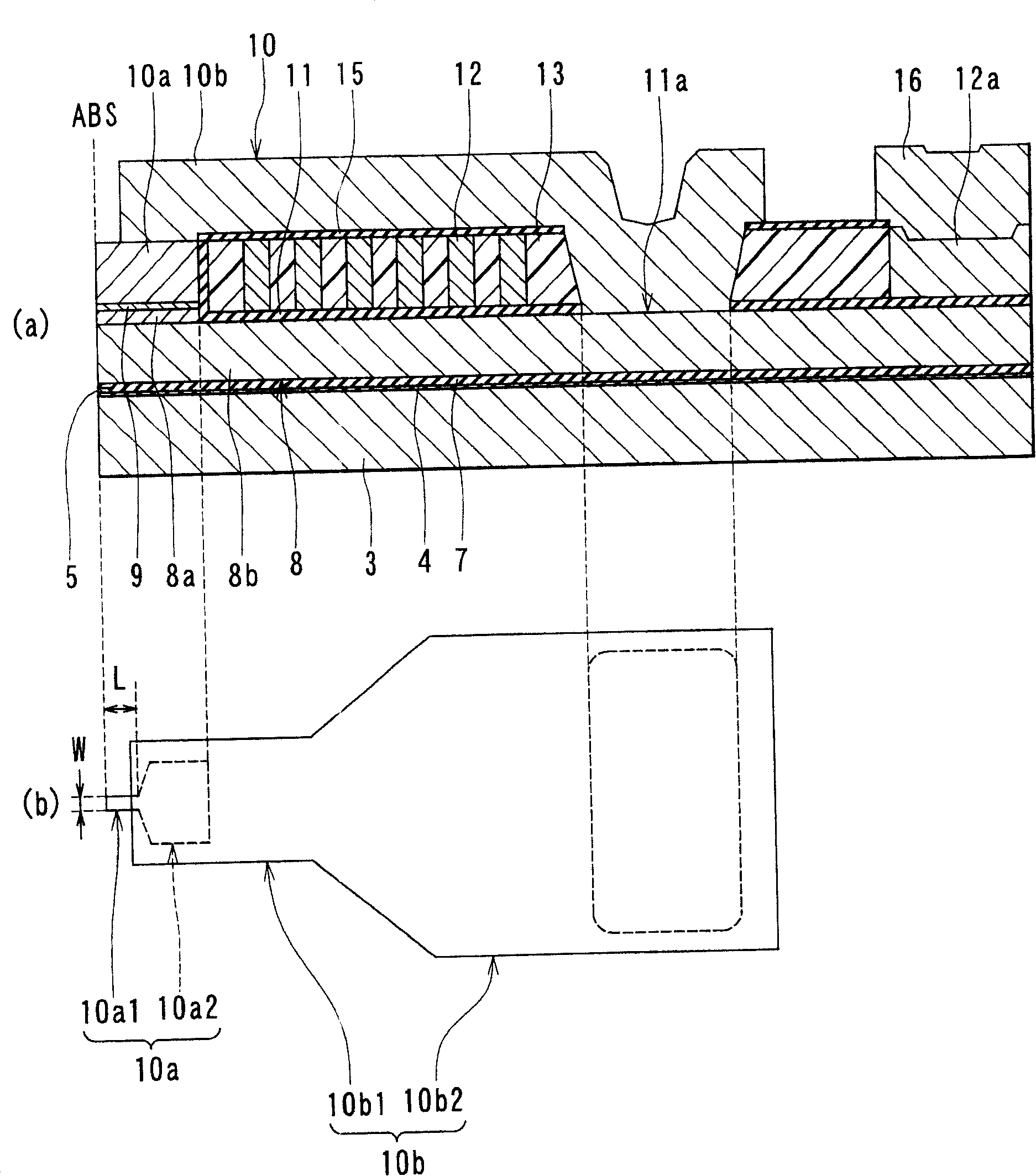
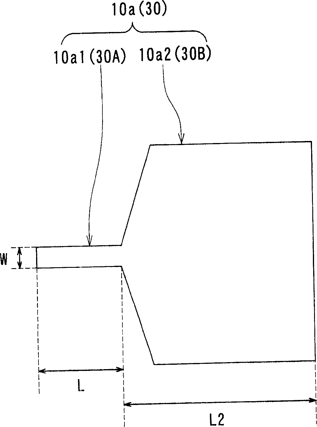
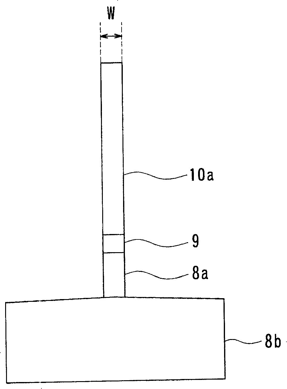
[0040] Hereinafter, embodiments of the present invention will be described in detail with reference to the drawings. First, refer to figure 1 and Figure 12 The structure of a thin film magnetic head according to an embodiment of the present invention will be described. figure 1 It is an explanatory diagram showing main parts of a thin-film magnetic head according to an embodiment of the present invention. exist figure 1 Among them, (a) shows a cross section perpendicular to the medium-facing surface and the substrate surface of the main part of the thin-film magnetic head. In addition, (b) shows the planar shape of the upper magnetic pole layer of the thin-film magnetic head. Figure 12 A cross section perpendicular to the medium-facing surface and the substrate surface of the thin-film magnetic head is shown.

[0041] The thin-film magnetic head of this embodiment is equipped with aluminum oxide·titanium carbide (Al 2 o 3 A substrate 1 made of a ceramic material such ...


PUM


Abstract

The lower magnetic pole layer has a magnetic pole part layer and a yoke part layer. The upper magnetic pole layer has a magnetic pole part layer and a yoke part layer. The magnetic pole portion layer of the lower magnetic pole layer, the recording gap layer, and the magnetic pole portion layer of the upper magnetic pole layer have the same cross-sectional shape parallel to the upper surface of the substrate. The assembly of the two magnetic pole portion layers and the recording gap layer includes a first portion having a width defining the track width and a second portion having a width greater than the width of the first portion. When the width of the first part is W and the distance from the media facing surface ABS to the boundary position of the first part and the second part is L, L / W is 2 or more and 5 or less. When the area of ​​the cross section of the assembly parallel to the upper surface of the substrate is S, S / (W×L) is 5 or more and 40 or less.

Description

technical field [0001] The invention relates to a thin-film magnetic head with at least an inductive electromagnetic conversion element and its manufacturing method, a magnetic head gimbal assembly including a thin-film magnetic head, and a hard disk device. Background technique [0002] In recent years, along with the increase in the areal recording density of hard disk devices, there has been a demand for continuous improvement in the performance of thin-film magnetic heads. As a thin-film magnetic head, a regenerative magnetic head with a magnetoresistive effect element for reading (hereinafter also referred to as MR (Magneto-resistive: magnetoresistive)) and an inductive element for writing are widely used. Composite thin-film magnetic head of the recording head of the electromagnetic conversion element. [0003] A recording head having a lower magnetic pole layer and an upper magnetic pole layer each including magnetic pole portions facing each other on opposite sides ...

Claims


Application Information

Patent Timeline
Patent Type & Authority Patents(China)
IPC IPC(8): G11B5/39G11B5/31
CPCG11B5/3906
Inventor 大池太郎野口洁矢里晴司
Owner TDK CORPARATION
Why Eureka
Eureka Blog
Learn More