
Brushless excitation synchronous generator

A technology for synchronous generators and main generators, which is applied in the direction of synchronous generators, electrical components, electromechanical devices, etc., and can solve the problem of unreasonable structure of brushless excitation synchronous generators, easy rectification modules being thrown out, rectification modules and pressure-sensitive The module has no problems such as protection devices, and achieves the effects of fixed stability, reliable structure, and reasonable wiring

Inactive Publication Date: 2011-01-26
CRRC YONGJI ELECTRIC CO LTD
View PDF0 Cites 0 Cited by
  • Summary
  • Abstract
  • Description
  • Claims
  • Application Information

AI Technical Summary

Problems solved by technology

[0003] In order to solve the problem that the structure of the existing brushless excitation synchronous generator is unreasonable, especially the problem that the rectifier module and the pressure sensitive module have no protection device, the invention provides a brushless excitation synchronous generator with improved structure
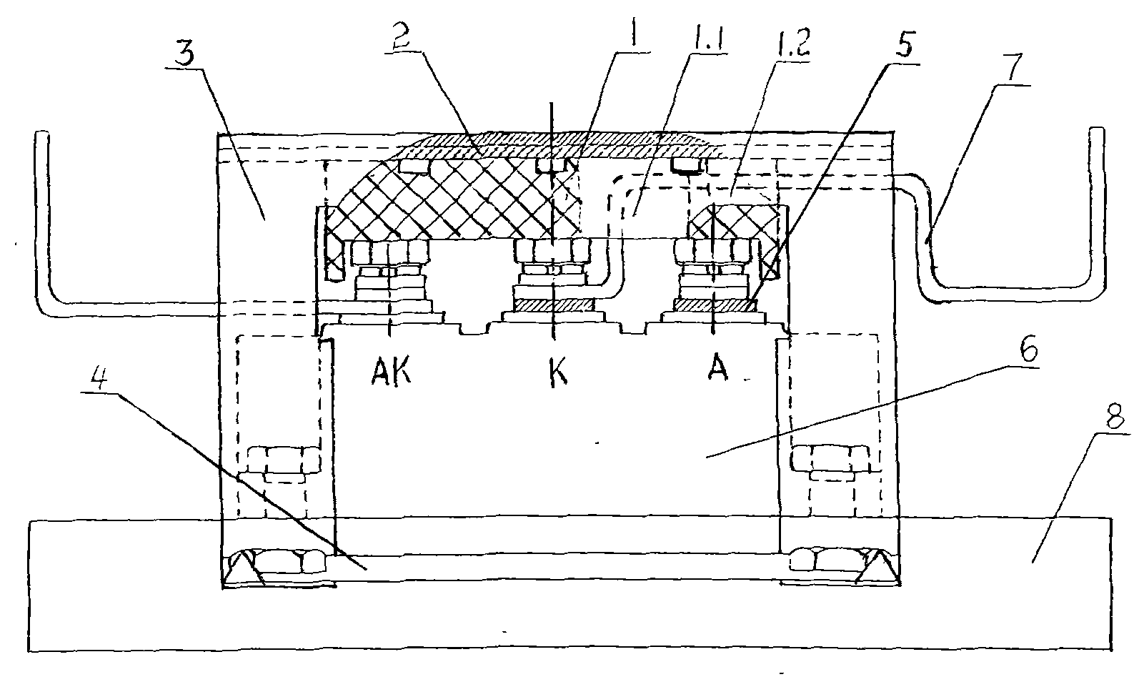
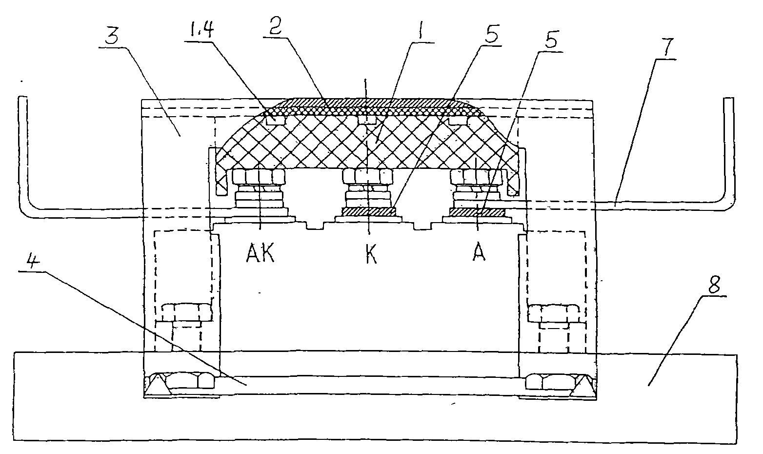
When the brushless excitation synchronous generator is working, the rotor of the main generator rotates at high speed, the centrifugal force on the pressure plate and the reaction force of the pressure cover neutralize it, the centrifugal force on the rectifier module and pressure sensitive module of the rectifier and the pressure plate Neutralize its reaction force, thus solving the problem that the rectifier module is easily thrown out due to centrifugal force

Method used


Image

  • Brushless excitation synchronous generator
  • Brushless excitation synchronous generator
  • Brushless excitation synchronous generator

Examples


Embodiment Construction

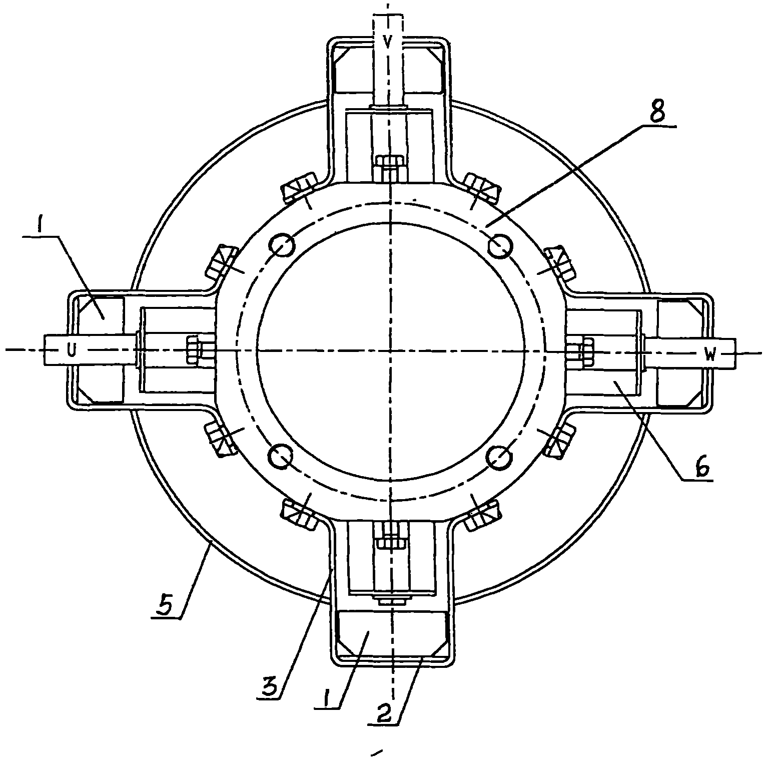
[0017] The brushless excitation synchronous generator includes a main generator and a rectifying device fixed on a rectifying wheel 8 coaxial with the rotor of the main generator. The rectifying device consists of three rectifying modules 6 and a pressure-sensitive module fixed on the rectifying wheel 8 It is formed by connecting two conductive rings 5 ​​respectively connected to the corresponding wiring bolts on the rectifier module 6 and the pressure-sensitive module. Two DC lead-out wires 7 are fixed on the rectifier device. The pressing plate 1 is covered with the pressing cover 3 fixed on the rectifying wheel 6 . A gasket 2 is provided between the pressure cover 3 and the upper surface of the pressure plate 1. The pressure cover 3 is made of a thin steel plate with a U-shaped cross-section. The locking pieces 4 are placed on the two feet on each side of the pressure cover 3, and then the locking pieces 4 and the feet of the pressure cover 3 are fastened on the rectifier w...


PUM


Abstract

The invention relates to a generator, in particular to a brushless excitation synchronous generator, which solves the problems of unreasonable structures in the existing brushless excitation synchronous generators. The brushless excitation synchronous generator comprises a main generator and a rectifier device fixed on a rectifier wheel of same axis as a main generator rotor; the rectifier deviceis formed by connecting three rectifier modules and a voltage sensitive module fixed on the rectifier wheel through two conducting rings respectively connected with corresponding connection bolts on the rectifier modules and the voltage sensitive module; two direct current leading-out wires are fixed on the rectifier device; and both the rectifier modules and the voltage sensitive module are provided with pressing boards which are covered by a pressing cover fixed on the rectifier wheel. Achieving the target of ensuring the rectifier modules and the two direct current leading-out wires not tobe thrown away easily during the working of the brushless excitation synchronous generator, and the brushless excitation synchronous generator enables the two direct current leading-out wires to be fixed more stably and the wiring to be more reasonable, thus forming a convenient and practical protection device with reliable structure.

Description

technical field [0001] The invention relates to a generator, in particular to a brushless excitation synchronous generator. Background technique [0002] The brushless excitation synchronous generator consists of a main generator, a rotating armature exciter coaxial with the main generator, and a rectifier fixed on the rectifier wheel coaxial with the main generator rotor. The rectifier is fixed on the rectifier wheel The three rectifier modules and one pressure-sensitive module are connected through two conductive rings respectively connected to the corresponding wiring bolts on the rectifier module and the pressure-sensitive module. The rectifier module and the pressure-sensitive module are vertically distributed in the radial direction of the rectifier wheel. direction. The three-phase output wires of the rotor winding of the exciter are connected to the input end of the rectification device, and the two conductive rings of the rectification device are respectively conne...

Claims


Application Information

Patent Timeline
Patent Type & Authority Patents(China)
IPC IPC(8): H02K11/00H02K19/26H02K11/042
Inventor 郑守海贺志学
Owner CRRC YONGJI ELECTRIC CO LTD
Learn More