Injection mechanism of injection machine

A technology for injection molding machines and injection cylinders, applied in the field of plastic machinery, can solve problems such as uneven force on the barrel screw, unstable movement, and instability, and achieve the effects of fast movement, stable operation, and reduced friction

Inactive Publication Date: 2009-08-05
CHANGSHENGDA MASCH ZHEJIANG CO LTD
View PDF0 Cites 9 Cited by
  • Summary
  • Abstract
  • Description
  • Claims
  • Application Information

AI Technical Summary

Problems solved by technology

[0002] The injection molding machine consists of a frame, a hopper installed on the frame, an injection mechanism, a template, and an opening and closing mold clamping mechanism that drives the template. The injection mechanism includes a guide rod bracket, an injection platform guide rod, an injection table, a hydraulic pressure Motor, injection cylinder and injection piston, as well as shifting cylinder and barrel screw, etc., the original injection mechanism has the following defects: First, there are guide sleeves on the bottoms of the rear plate of the injection platform and the front plate of the injection platform. The guide rod of the injection platform is matched, and the torque of the rear plate of the injection platform is always changing due to the deformation of the guide rod and the friction between the guide rod and the guide sleeve during the movement process, resulting in uneven force on the barrel screw and unstable action; The hydraulic motor and the valve plate are connected by a hose, and the force on the rear plate of the injection platform positioning the hydraulic motor is different at different positions; the third is that the hydraulic motor is fixed on the rear plate of the injection platform, and the injection cylinder is fixed on the injection platform. On the front plate of the injection platform, there is relative movement between the hydraulic motor and the injection cylinder, which is unstable; fourth, the guide of the rear plate of the injection platform is the same as the front plate of the injection platform, which is guided by a guide rod, and its own friction makes the mechanical back pressure always exist

Method used


Image

  • Injection mechanism of injection machine
  • Injection mechanism of injection machine
  • Injection mechanism of injection machine

Examples


Embodiment Construction

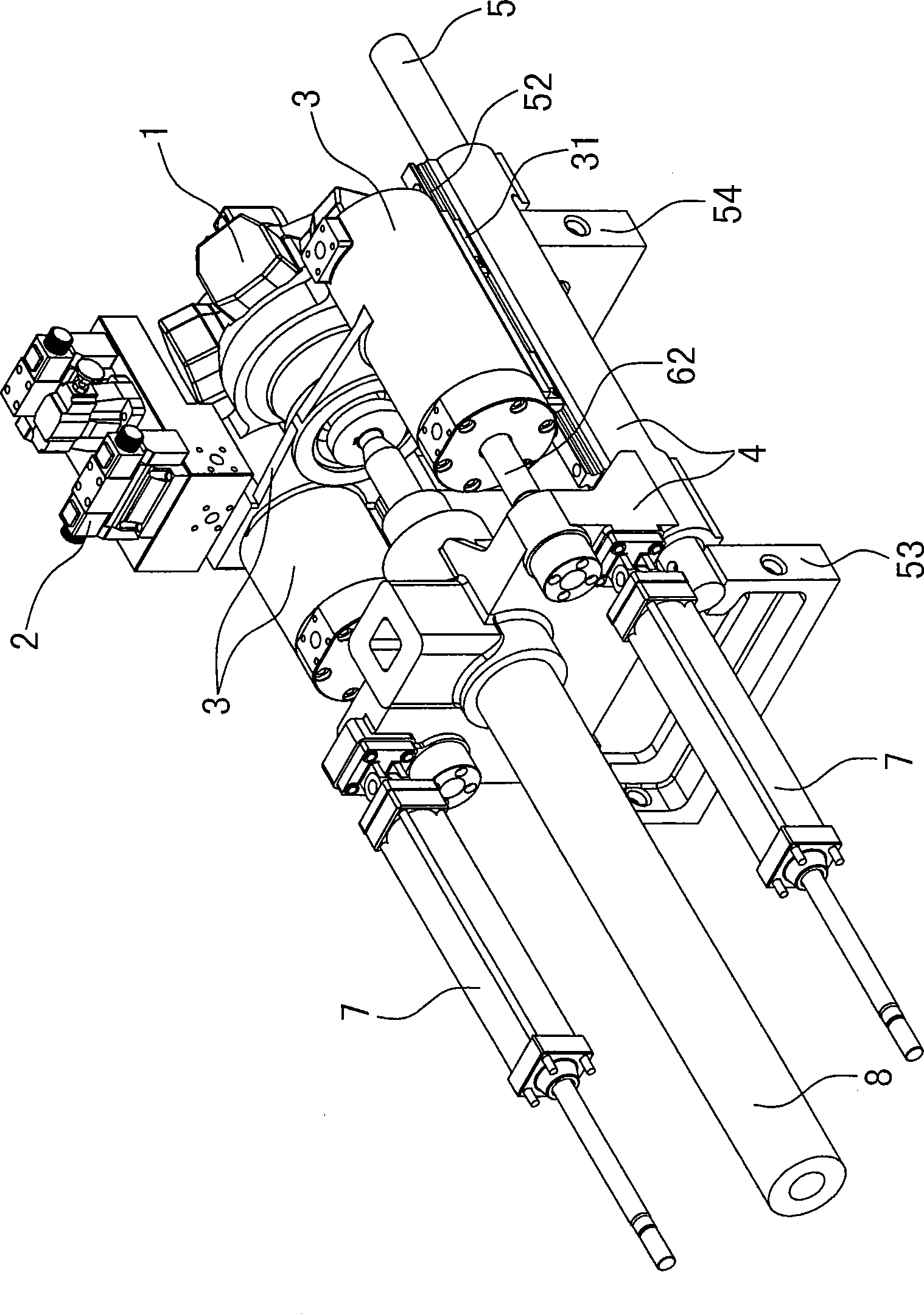
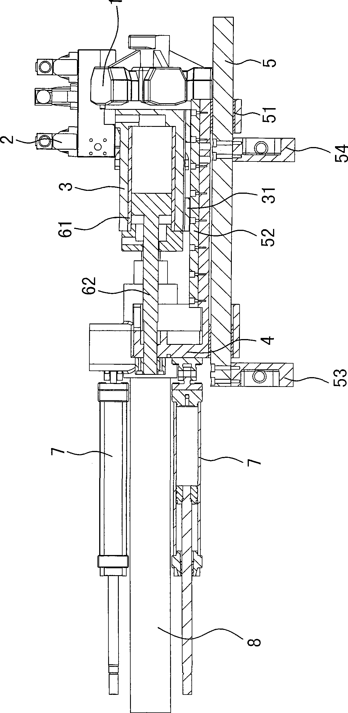
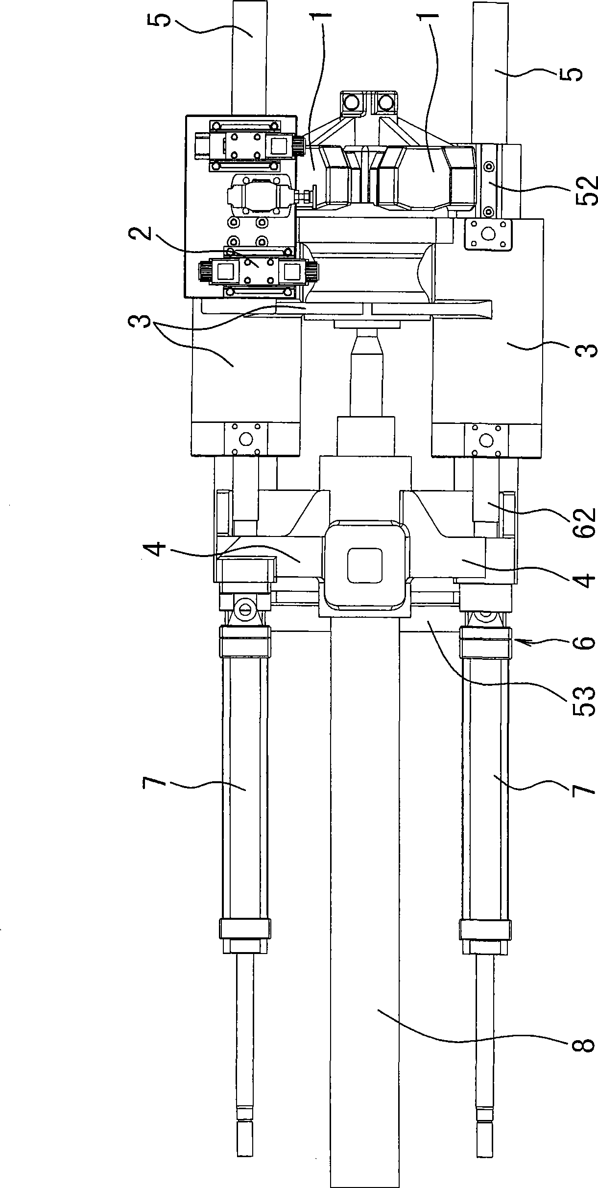
[0011] The invention discloses an injection mechanism of an injection molding machine, such as figure 1 — Figure 4 As shown, it includes the front and rear guide rod brackets 53, 54, the front and rear guide rod brackets are equipped with the injection platform guide rod 5, the injection platform front plate 4 and the injection platform rear plate 3 are arranged on the injection platform guide rod, and the injection platform front plate 4. It is connected with the moving cylinder assembly 7 and the barrel screw 8. The barrel screw 8 is driven by the hydraulic motor 1 and the injection cylinder 61. The hydraulic motor 1 is connected with the rear plate 3 of the injection platform. It is characterized in that the rear plate 4 of the injection platform The linear guide rail 52 is installed on the upper part, and the slider 31 is installed on the lower part of the rear plate 3 of the injection platform. . The motion guiding platform in the whole mechanism is the front plate 4 o...


PUM


Abstract

The invention provides an injection mechanism for injection molding machines, which comprises a front guide bar support and a back guide bar support, wherein an injection-table guide bar is arranged on the front guide bar support and the back guide bar support; an injection-table front plate and an injection-table back plate are arranged on the injection-table guide bar; the injection-table front plate is connected with an oil-cylinder integral shifting component and a charging barrel screw; the charging barrel screw is driven by a hydraulic motor and an injection oil cylinder; and the hydraulic motor is connected with the injection-table back plate. The injection mechanism is characterized in that the rear part of the injection-table front plate is provided with a linear guide rail; the lower part of the injection-table back plate is provided with a slider; the slider is matched with the linear guide rail; and the hydraulic motor, an injection valve plate component and the injection oil cylinder are fixed on the injection-table back plate. As the injection-table front plate and the injection-table back plate in the structure fit through the linear guide rail, injection, injection withdraw and material storage are all guided through the linear guide rail; the injection mechanism is fast in motion and accurate to position, reduces the mechanical back pressure of stored material to minimum, and enables the stored material to be uniform; and integral shifting action is relatively independent of the guidance of injection, injection withdraw and material storage.

Description

technical field [0001] The invention relates to an injection molding machine, in particular to an injection mechanism of an injection molding machine, and belongs to the field of plastic machinery. Background technique [0002] The injection molding machine consists of a frame, a hopper installed on the frame, an injection mechanism, a template, and an opening and closing mold clamping mechanism that drives the template. The injection mechanism includes a guide rod bracket, an injection platform guide rod, an injection table, a hydraulic pressure Motor, injection cylinder and injection piston, as well as shifting cylinder and barrel screw, etc., the original injection mechanism has the following defects: First, there are guide sleeves at the bottom of the rear plate of the injection platform and the front plate of the injection platform. The guide rod of the injection platform is matched, and the torque of the rear plate of the injection platform is always changing due to th...

Claims


Application Information

Patent Timeline
Patent Type & Authority Applications(China)
IPC IPC(8): B29C45/46B29C45/47
Inventor 陈一青汪军建
Owner CHANGSHENGDA MASCH ZHEJIANG CO LTD
Why Eureka
Try Eureka