Supercharge Your Innovation With Domain-Expert AI Agents!

Recording apparatus

一种记录装置、驱动力的技术,应用在记录装置领域,能够解决成本增高等问题,达到减少配设件数、实现装置的简化和小型化、降低制造成本的效果

Inactive Publication Date: 2009-08-05
ALPS ALPINE CO LTD
View PDF1 Cites 10 Cited by
  • Summary
  • Abstract
  • Description
  • Claims
  • Application Information

AI Technical Summary

Problems solved by technology

Furthermore, if a UD motor is used as a CR motor, since the UD motor is not a very large motor, it must be changed to a large-capacity motor, which will increase the cost.

Method used


Image

  • Recording apparatus
  • Recording apparatus
  • Recording apparatus

Examples


Embodiment Construction

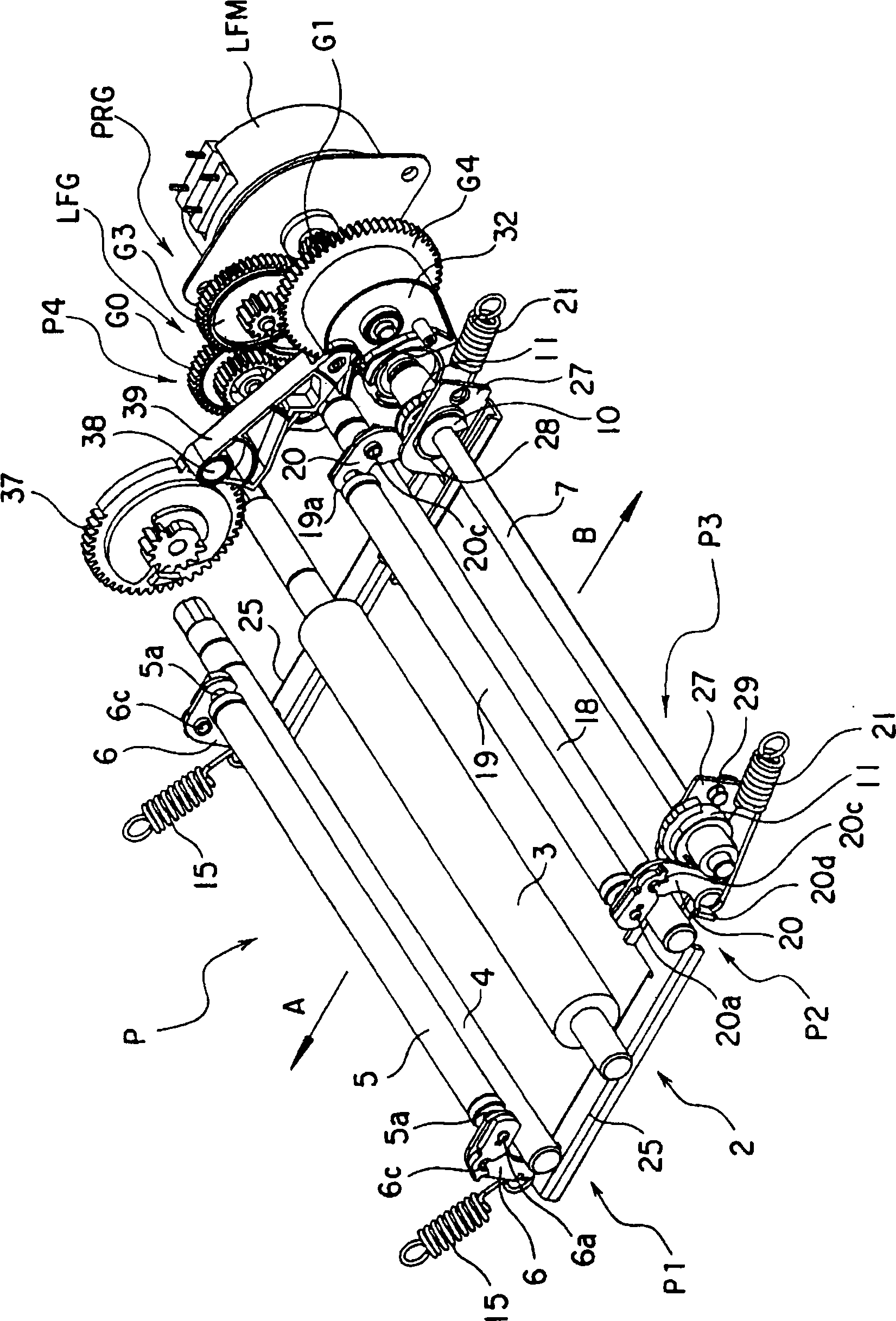
[0030] The following will be based on Figure 1 to Figure 16 Embodiments of the recording device of the present invention will be described.

[0031] Such as figure 1 As shown, the recording device P of this embodiment is equipped with a printing mechanism 2 on the middle part of the recording paper transport path. 2 The desired image can be printed on recording paper (not shown in the drawing) such as photographic paper.

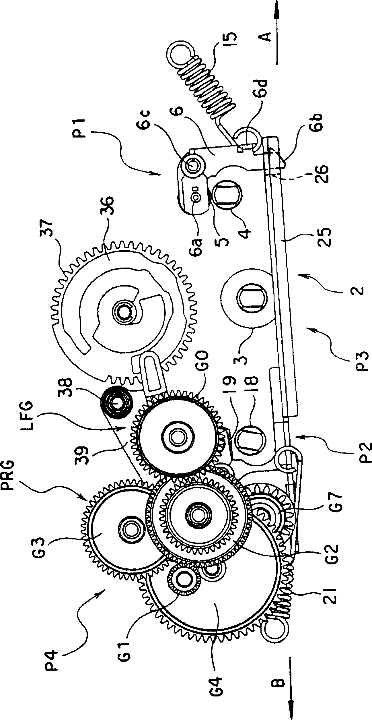
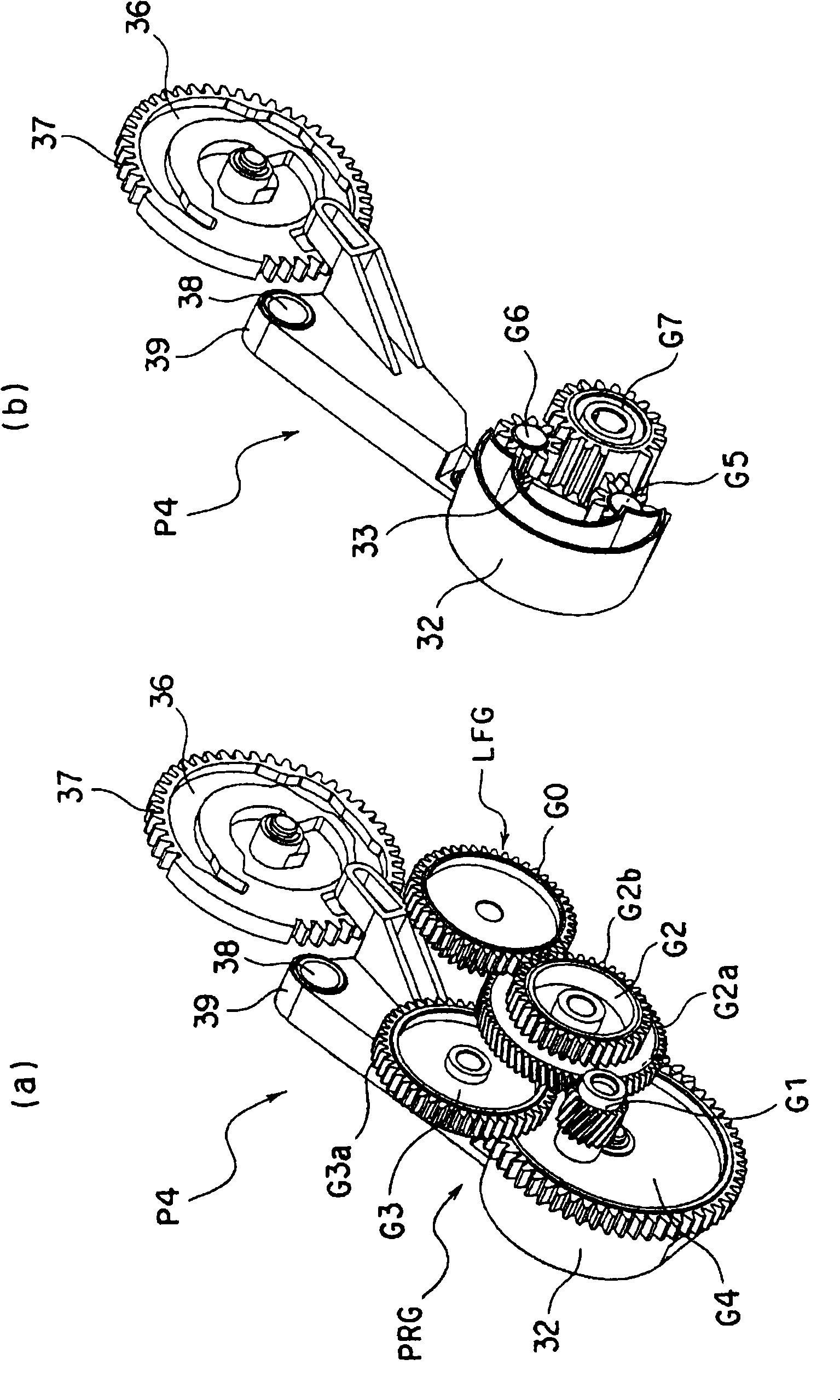
[0032] The above-mentioned printing mechanism 2 includes a cylindrical platen roller 3 and a thermal head (not shown in the drawings). Between the frames, the platen roller 3 is rotatable by the driving force for conveying the paper transmitted by the LF motor LFM, and the thermal head can contact and separate from the platen roller 3 by the driving force of the UD motor (not shown).

[0033] Moreover, the first paper feeding mechanism P1 is arranged on the downstream side of the left side of the platen roller 3 in the drawing in the direction of the arrow...


PUM


Abstract

A recording apparatus is provided, in which an LF motor is as a pressure release mechanism to make the apparatus small-sized, including a printing unit that contacts or separates a thermal head with or from a platen using the driving force of a UD motor, one or more sheet feed units that include sheet feed rollers which are rotated forward or backward by the driving force of an LF motor transmitted through a transport gear group and pressure rollers which are supported between a pair of roller supporting members and are urged by elastic members to come into pressure contact with the sheet feed rollers, and are provided on an upstream side and a downstream side of the printing unit in a transport path of a recording sheet, a pressure release mechanism including a cam shaft that is rotatably provided so as to tilt the pair of roller supporting members of the sheet feed units against the urging force of the elastic members and separates the pressure rollers from the sheet feed rollers, and a pressure release gear group that transmits the driving force of the LF motor to the cam shaft of the pressure release mechanism, the driving force of the LF motor being transmitted to the pressure release gear group and the transport gear group.

Description

technical field [0001] The present invention relates to a recording device capable of printing all over without leaving blanks on recording paper, and more particularly to a recording device capable of simplifying and reducing the cost of a paper feeding mechanism. Background technique [0002] The recording device shown in Patent Document 1, which can print all over the recording paper without leaving blanks, includes a first paper feeding mechanism and a second paper feeding mechanism. The upstream side of the paper conveying direction, and the second paper feeding mechanism is arranged on the downstream side. Each paper feed mechanism includes a paper feed roller that is rotatably driven by the driving force of the drive source LF motor, and a pressure contact roller that is pressed against the paper feed roller by the driving force of the drive source CR motor. In each of the paper feeding mechanisms, the recording paper is pressed between the paper feeding roller and t...

Claims


Application Information

Patent Timeline
Patent Type & Authority Applications(China)
IPC IPC(8): B41J2/32B41J23/02B41J11/00
CPCB41J13/025
Inventor 阿部荣文佐藤稔本木善幸濑津荣彬
Owner ALPS ALPINE CO LTD
Features
  • R&D
  • Intellectual Property
  • Life Sciences
  • Materials
  • Tech Scout
  • Unparalleled Data Quality
  • Higher Quality Content
  • 60% Fewer Hallucinations
Learn More