Travel controller of hydraulic drive vehicle

A driving control and hydraulic technology, which is applied in the direction of control devices, transmission devices, fluid transmission devices, etc., can solve the problem of large impact and achieve the effect of preventing rapid advance

Inactive Publication Date: 2009-08-05
NIHON KENKI CO LTD
View PDF2 Cites 4 Cited by
  • Summary
  • Abstract
  • Description
  • Claims
  • Application Information

AI Technical Summary

Problems solved by technology

Therefore, if you step on the travel pedal quickly when driving forward or at a low speed, the vehicle will be driven forward or accelerated rapidly, and the impact will be very large.

Method used


Image

  • Travel controller of hydraulic drive vehicle
  • Travel controller of hydraulic drive vehicle
  • Travel controller of hydraulic drive vehicle

Examples


Embodiment Construction

[0020] Below, refer to Figure 1~6 Embodiments of the travel control device for a hydraulically driven vehicle according to the present invention will be described.

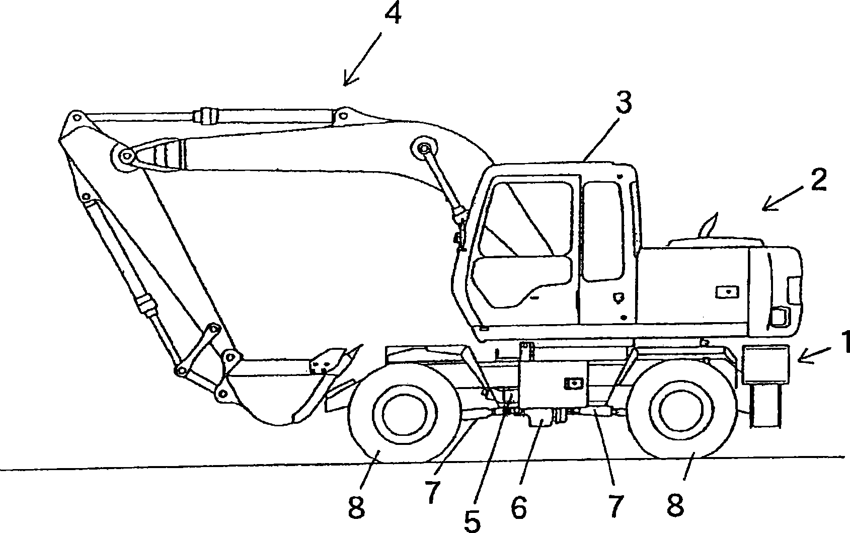
[0021] figure 1 A wheeled hydraulic excavator to which the first embodiment of the present invention is applied is shown. This wheeled hydraulic excavator includes an undercarriage 1 and a revolving upper body 2 rotatably mounted on an upper portion of the undercarriage 1 . A cab 3 and a front attachment 4 for work are provided on the upper revolving body 2 . The undercarriage 1 is provided with a traveling hydraulic motor 5 , a gearbox 6 , a transmission shaft 7 , and tires 8 .

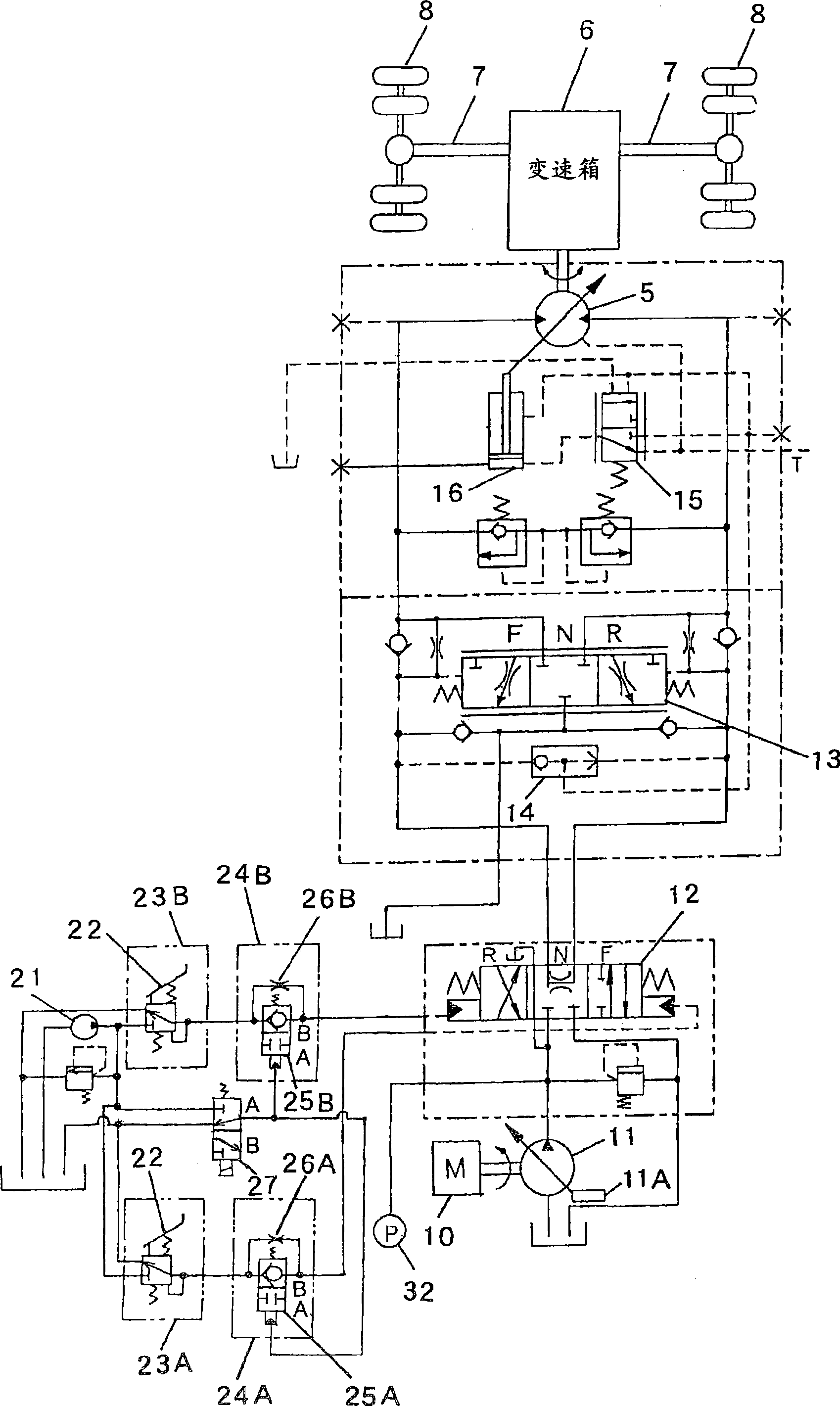
[0022] figure 2 It is a hydraulic circuit diagram for traveling of the wheel hydraulic excavator according to the present embodiment. Such as figure 2 As shown, hydraulic oil from a hydraulic pump 11 driven by an engine 10 is controlled in direction and flow rate by a control valve 12 , and is supplied to the travel hydraulic mo...


PUM


Abstract

A traveling control device for a hydraulically-driven vehicle includes: a traveling hydraulic motor driven by oil delivered from a hydraulic pump; a speed-reducing mechanism with an adjustable speed-reduction ratio, that slows down rotation of the hydraulic motor and transmits the slowed rotation to wheels; a pressure oil control device that controls a flow of pressure oil from the hydraulic pumpto the hydraulic motor in correspondence to an extent to which a traveling pedal is operated; a speed-reduction ratio detection device that detects the speed-reduction ratio at the speed-reducing mechanism; and an acceleration limiting device that restricts accelerating operation of the hydraulic motor achieved in response to an operation of the traveling pedal, when an acceleration-limiting condition, that is, the speed-reduction ratio detected by the speed-reduction ratio detection device is equal to or greater than a predetermined value, is met.

Description

technical field [0001] The invention relates to a driving control device for a hydraulically driven vehicle such as a wheeled hydraulic excavator. Background technique [0002] In such a hydraulically driven vehicle, a control valve is driven by a pilot pressure generated by operating a traveling pedal, whereby hydraulic oil discharged from a hydraulic pump is supplied to a traveling hydraulic motor through a main line, and the vehicle is driven (see Patent Document 1 ). In Patent Document 1, there is a variable relief valve that relieves hydraulic oil from a main line, and the relief pressure of the variable relief valve is controlled based on a pilot pressure generated by operating a pedal. [0003] Patent Document 1: Japanese Patent Application Laid-Open No. 6-193730. [0004] In the hydraulically driven vehicle described in Patent Document 1, the relief pressure increases as the pilot pressure increases. Therefore, if the travel pedal is quickly depressed when driving...

Claims


Application Information

Patent Timeline
Patent Type & Authority Applications(China)
IPC IPC(8): F16H47/02F16H61/00F16H61/40F16H59/06F16H59/44F16H59/70F16H61/66F16H61/682E02F9/22F16H61/4183F16H61/42F16H61/68
CPCB60W2540/10B60W2520/10F16H2059/6861F16H61/4061F16H59/70F16H61/4035F16H61/4148B60W2710/1044F16H59/44F16H61/478F16H61/47B60W2540/16F16H47/02F16H59/06F16H61/40
Inventor 小高克明佐竹英敏
Owner NIHON KENKI CO LTD
Why Eureka
Try Eureka