Coal-fired power plant turbulent burner suitable for low-order mixed coal combustion

A swirl burner and mixed coal combustion technology, applied in the burners, burners, combustion methods and other directions of burning powder fuel, can solve the problem of aggravating the overheating temperature of the furnace outlet superheater and slagging, shortening the effective combustion residence time, and boiler flying. The increase of carbon content in ash and other problems can solve the problem of local over-temperature at the outlet, eliminate the phenomenon of hypoxia, and reduce the generation of NOx.

Active Publication Date: 2016-03-16
STATE GRID HEBEI ENERGY TECH SERVICE CO LTD
View PDF10 Cites 2 Cited by
  • Summary
  • Abstract
  • Description
  • Claims
  • Application Information

AI Technical Summary

Problems solved by technology

Because the combustible coal burns first, and at the same time consumes a lot of oxygen in the mixed combustion area, the oxygen in the primary air outlet area of ​​the burner is quickly exhausted, forming a low-oxygen area, and this position is exactly the position where the refractory coal starts to ignite , in this low-oxygen area, due to the adverse effects of self-flammability and external hypoxia, the combustion of difficult-to-burn coal becomes worse, which is manifested as difficulty in ignition of difficult-to-burn coal, delayed combustion, and difficult A large number of unburned coal particles can only be fully combusted in the oxygen-sufficient area of ​​the upper part of the furnace, resulting in an increase in the temperature of the furnace outlet, shortening the effective combustion residence time in the furnace, deteriorating the degree of burnout, and increasing the carbon content of boiler fly ash , the unburned heat loss increases, and the temperature rise of the furnace outlet will aggravate the hazards such as overheating and slagging of the superheater at the furnace outlet

Method used


Image

  • Coal-fired power plant turbulent burner suitable for low-order mixed coal combustion
  • Coal-fired power plant turbulent burner suitable for low-order mixed coal combustion

Examples


Embodiment Construction

[0022] The present invention will be described in detail below in conjunction with the accompanying drawings and specific embodiments.

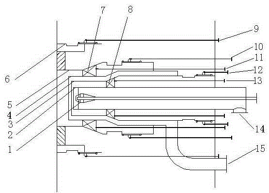
[0023] See attached figure 1 , the present invention includes a cone body 1, an inner primary air casing 2 set on the periphery of the central cone body 1, an inner secondary air casing 3 set on the periphery of the inner primary air casing 2, and an inner secondary air casing set on the inner secondary air casing 3, the outer primary air casing 4 on the periphery and the outer secondary air casing 5 set on the periphery of the outer primary air casing 4; the inner primary air casing 2 is enclosed to form an inner primary air passage, and the inner secondary air casing 3 and the inner primary air casing 2 to form an inner secondary air passage, the inner secondary air casing 3 and the outer primary air casing 4 form an outer primary air passage, and the outer primary air casing 4 and The outer secondary air casing 5 is enclosed to form an ou...


PUM


Abstract

The invention discloses a coal-fired power plant turbulent burner suitable for low-order mixed coal combustion. The coal-fired power plant turbulent burner comprises a cone, an inner primary air shell, an inner secondary air shell, an outer primary air shell, an outer secondary air shell and a surrounding air shell, wherein the center cone is sleeved with the inner primary air shell, the inner primary air shell is sleeved with the inner secondary air shell, the inner secondary air shell is sleeved with the outer primary air shell, the outer primary air shell is sleeved with the outer secondary air shell, and the surrounding air shell is arranged on the outer side of the outer secondary air shell. An inner primary air channel is defined by the inner primary air shell, an inner secondary air channel is defined by the inner secondary air shell and the inner primary air shell, an outer primary air channel is defined by the inner secondary air shell and the outer primary air shell, an outer secondary air channel is defined by the outer primary air shell and the outer secondary air shell, and a surrounding air channel is formed outside the turbulent burner. By the adoption of the coal-fired power plant turbulent burner, the problem that air is insufficient when different types of coal of the large combustion difficulty characteristic difference are mixed and burned at a single primary air nozzle of a traditional turbulent burner is solved, and ignition and combustion of the types of coal difficult to burn can be promoted.

Description

technical field [0001] The invention relates to the field of coal-fired boilers, in particular to a swirl pulverized coal burner, and is especially suitable for boilers that burn mixed coal. Background technique [0002] Thermal power plants account for more than 80% of my country's electric power industry. Coal-fired power plant boilers are designed according to specific coal types. Depending on the type of coal designed, the furnace type, structure and burner selection of the boiler will also be different. The coal type based on which the boiler is designed is the design coal type, which is the best "suitable furnace" coal type. However, with the marketization of domestic thermal coal supply and the continuous increase of domestic large-scale coal-fired power plants, in fact almost all domestic power plants are burning non-design coal. Moreover, in order to pursue the greatest economy, it has become the "normal" operation mode of most thermal power plants to burn a larg...

Claims


Application Information

Patent Timeline
Patent Type & Authority Applications(China)
IPC IPC(8): F23D1/02
Inventor 魏刚米翠丽张勇胜樊孝华闫慧博贾永会
Owner STATE GRID HEBEI ENERGY TECH SERVICE CO LTD
Why Eureka
Try Eureka