Optical cable switching box and its production method
A technology of optical cable splicing and manufacturing methods, which is applied in the direction of fiber mechanical structure, etc., can solve the problems of unfavorable overhaul and maintenance, high rate of repeated rework, high production cost, etc.
- Summary
- Abstract
- Description
- Claims
- Application Information
AI Technical Summary
Problems solved by technology
Method used
Image
Examples
Embodiment 1
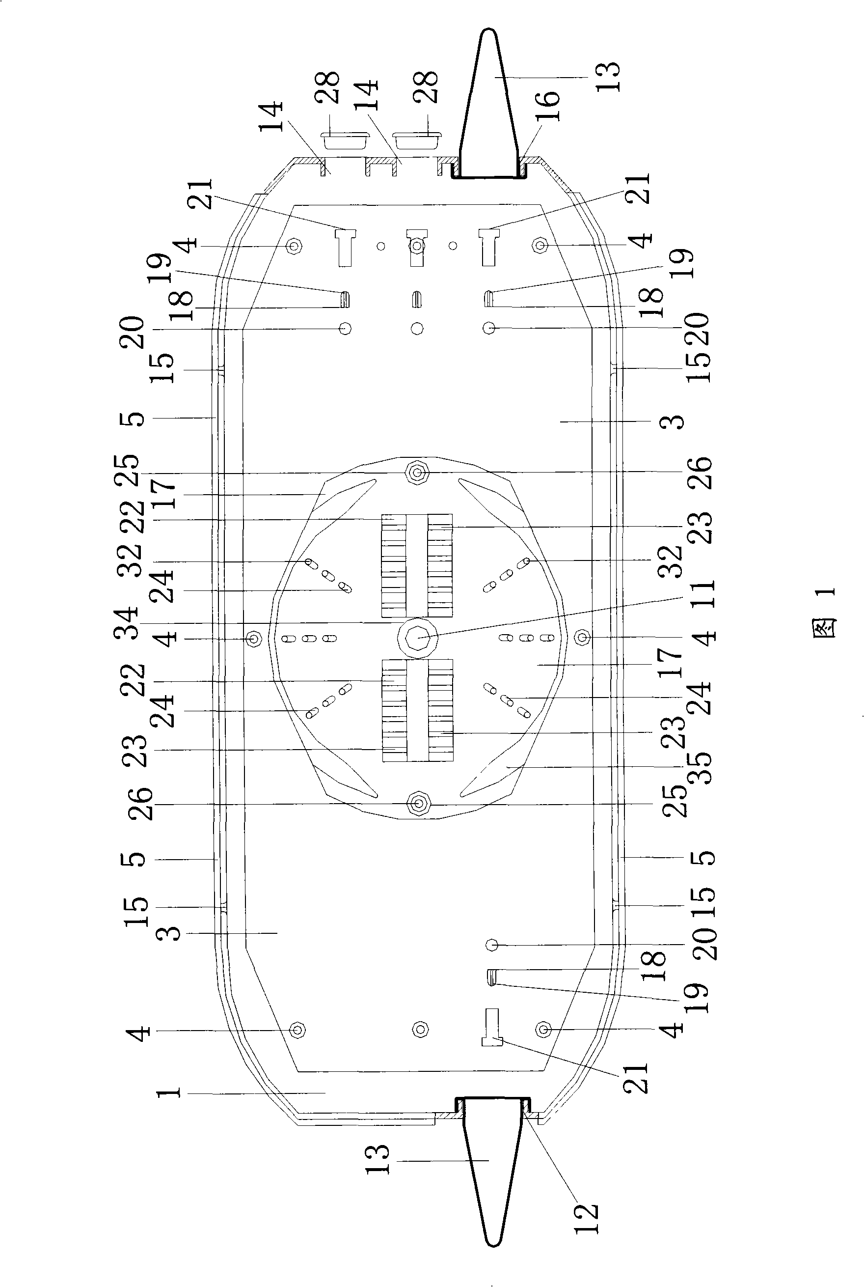
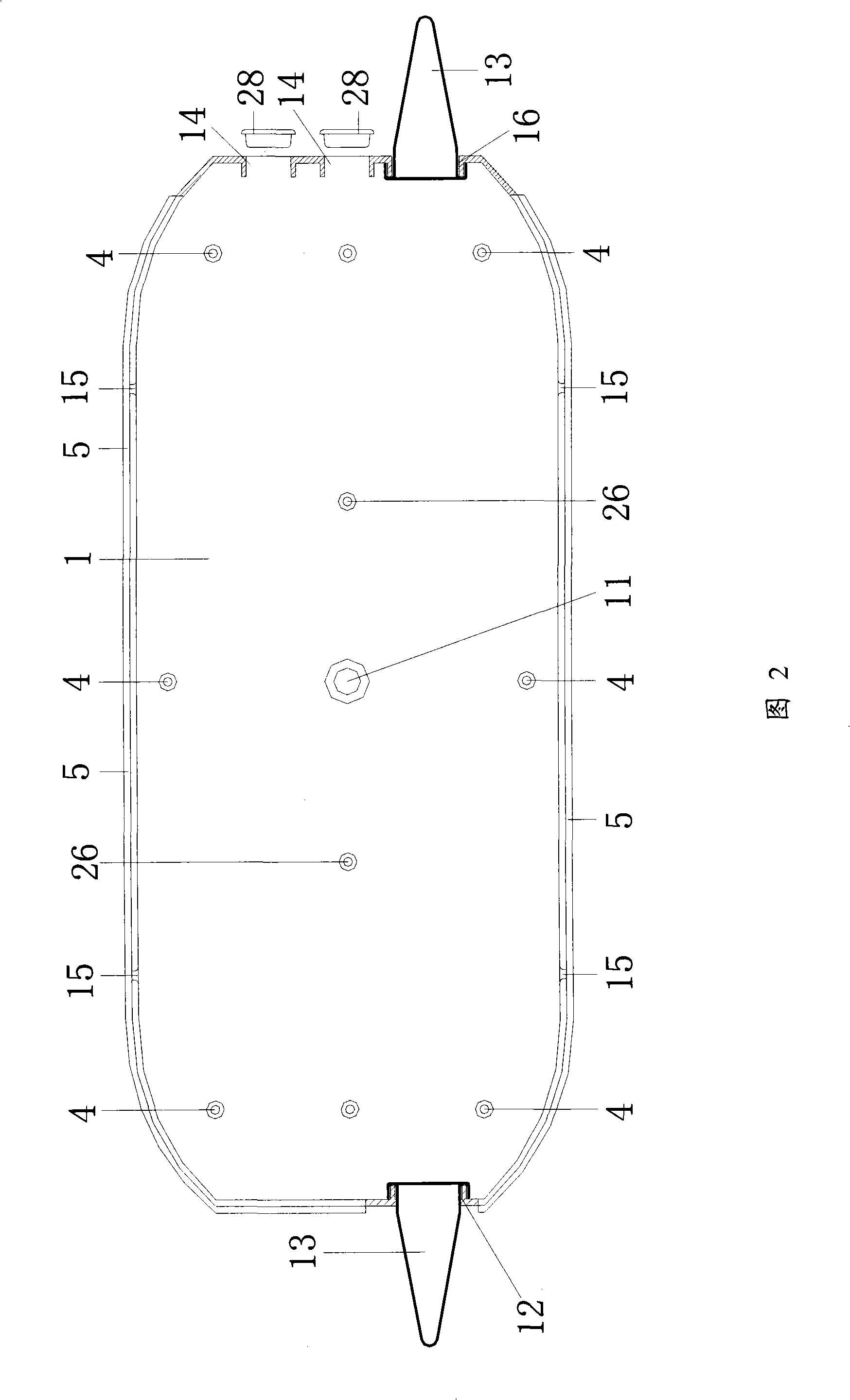
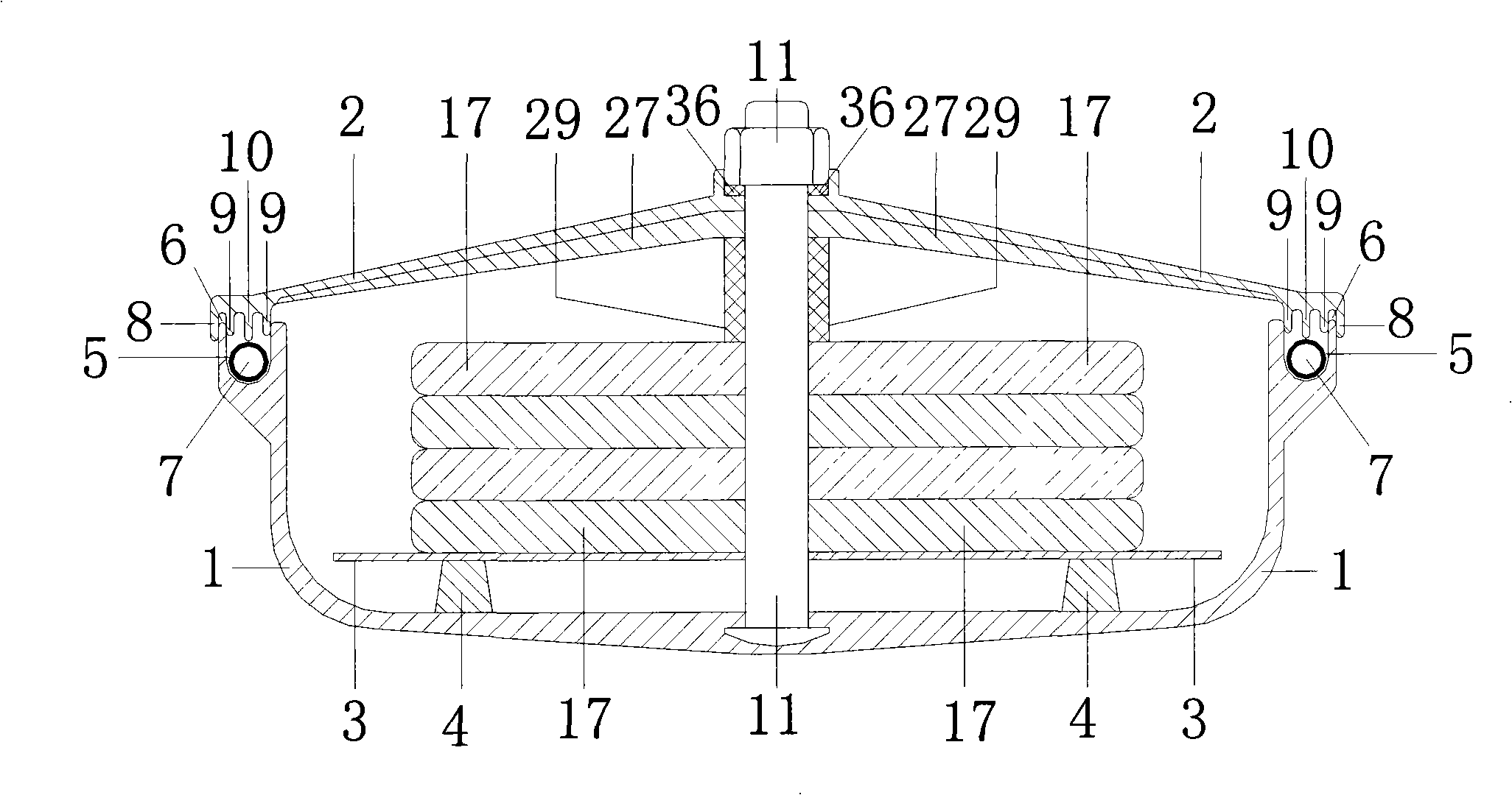
[0118] It is composed of the main body of the splicing box (1), the main splicing bracket (3), the fiber tray (17) and the upper cover of the splicing box (2). ) box to accommodate the connection assembly bracket (3) and the fiber tray (17), the connection box main body (1) is provided with a sealing groove (5), the base column of the assembly bracket (4), and the positioning column of the fiber tray (26), closed fastening bolt structure (11), optical cable inlet hole (12), optical cable outlet hole (16), leather wire optical cable outlet hole (14) and reserved hole (15).
[0119] A sealing groove (5) is provided on the outside of the upper edge of the main body (1) of the connection box, and the sealing groove (5) surrounds the outer side of the upper edge. The overall cross-sectional shape of the sealing groove (5) is U-shaped, and the sealing groove (5) The section shape of the bottom is arc-shaped, and an annular hollow sealing strip (7) is placed in the sealing groove (5)...
Embodiment 2
[0128] The main body (1) of the connection box is placed at the bottom of the box, and the overall connection bracket (3) is placed. The shape of the connection bracket (3) matches the main body (1) of the connection box. The bracket fastening holes (33) are arranged in the middle and the middle, and the bracket fastening holes (33) correspond to the main bracket base column (4) at the bottom of the connection box main body (1). The bracket (3) is fastened on the base column (4) of the general support bracket, and the central part of the connection total support bracket (3) is provided with a fastening bolt hole (34), and the fastening bolt hole (34) is connected with the main body of the connection box (1) The closed fastening bolt structure (11) at the bottom is corresponding.
[0129] Connect the middle part of the overall support bracket (3), set the fiber-container tray positioning holes (25) on both sides corresponding to the fastening bolt holes (34), the fiber-containe...
Embodiment 3
[0133] The overall shape of the fiber-container tray (17) is tray-shaped, and it is arranged on the continuous support bracket (3). (35) prevent the connected optical fiber from overflowing to the outside of the fiber tray (17), causing failure.
[0134] The two ends of the fiber containing tray (17) are provided with positioning holes (25) for the fiber containing tray. The positioning holes (25) of the fiber containing tray (25) correspond to the positioning columns (26) of the fiber containing tray (26). The bolt hole (34), the fastening bolt hole (34) is corresponding to the closed fastening bolt structure (11) at the bottom of the connection box main body (1).
[0135] There are at least two optical fiber connector support brackets (22) between the fastening bolt holes (34) and the positioning holes (25) of the fiber tray (25), and the optical fiber connector support brackets (22) are relatively provided with optical fiber connector embedded grooves (23) , at least 12, t...
PUM
 Abstract
Description
Claims
Application Information
 - R&D
- Intellectual Property
- Life Sciences
- Materials
- Tech Scout
- Unparalleled Data Quality
- Higher Quality Content
- 60% Fewer Hallucinations
Browse by: Latest US Patents, China's latest patents, Technical Efficacy Thesaurus, Application Domain, Technology Topic, Popular Technical Reports.
© 2025 PatSnap. All rights reserved.Legal|Privacy policy|Modern Slavery Act Transparency Statement|Sitemap|About US| Contact US: help@patsnap.com


