Power supply connector assembly

A technology of power connectors and socket connectors, which is applied in the direction of connection, parts of connection devices, electrical components, etc., and can solve problems such as reducing the strength of the top wall of the insulating body

Active Publication Date: 2009-08-12
立全科技(太仓)有限公司
View PDF0 Cites 10 Cited by
  • Summary
  • Abstract
  • Description
  • Claims
  • Application Information

AI Technical Summary

Problems solved by technology

Further, the more heat dissipation through holes, although the heat dissipation effect will be improved, but at the same time, the strength of the top wall of the insulating body will be reduced

Method used


Image

  • Power supply connector assembly
  • Power supply connector assembly
  • Power supply connector assembly

Examples


Embodiment Construction

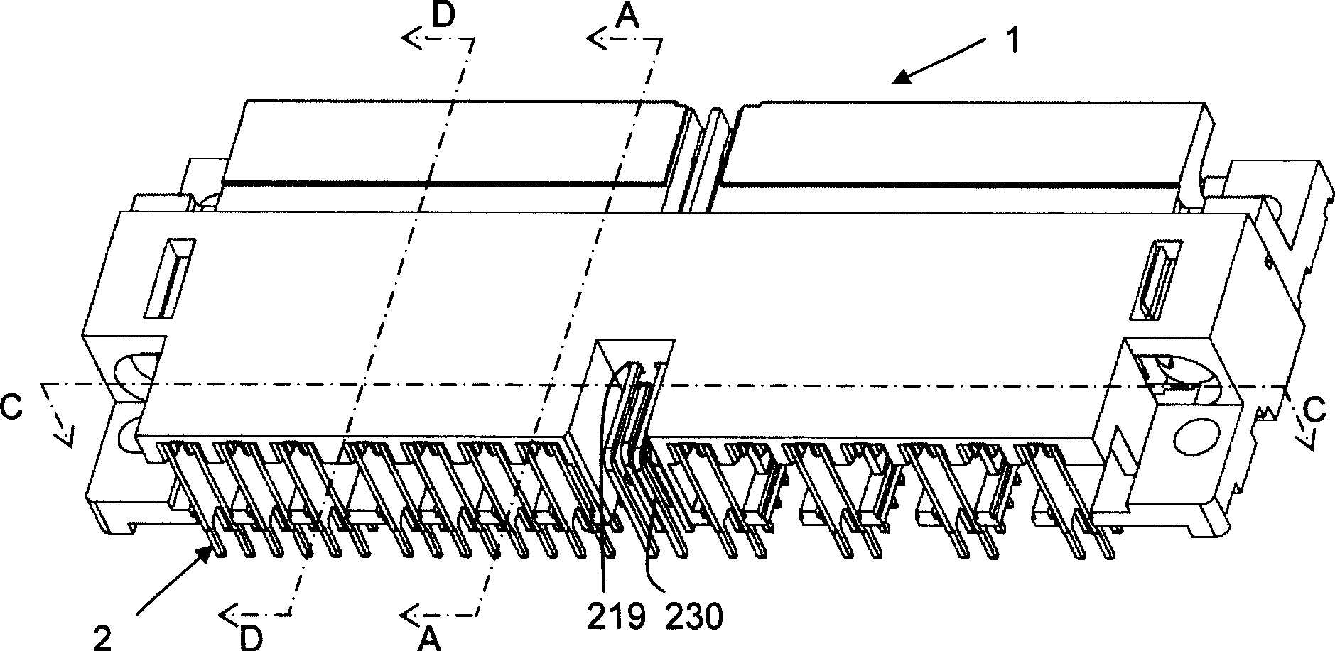
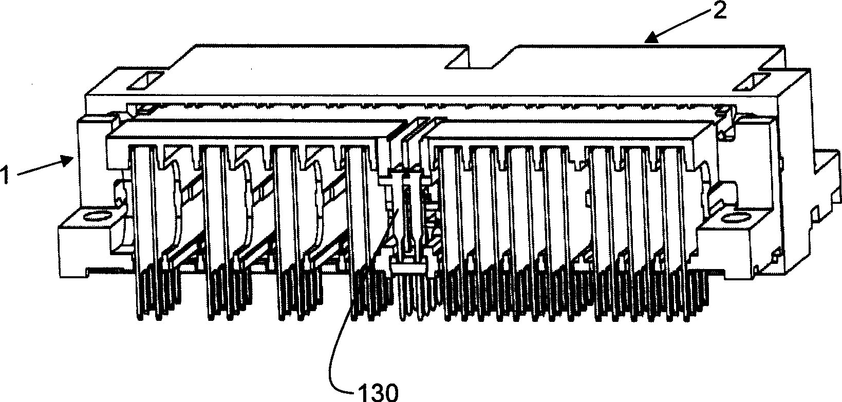
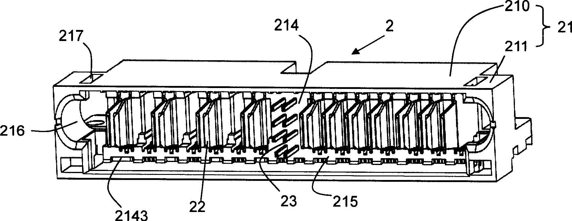
[0034] see figure 1 , 2 As shown, the power connector assembly of the present invention includes two power connectors that are paired with each other and realize high-voltage and high-current transmission through their respective power terminals, which are respectively the first power connector and the second power connector, The first power connector includes a first insulating body and several first power terminals installed in the first insulating body, and the second power connector includes a second insulating body and several second power terminals installed in the insulating body. In the mode, the first power connector is the socket connector 2, the second power connector is the plug connector 1, the first power terminal installed on the socket connector 2 is a female terminal, and the second power terminal installed on the plug connector 1 It is a male terminal, and the plug connector 1 and the socket connector 2 are used to be respectively installed on a circuit boar...


PUM


Abstract

The invention discloses a power supply connector component, which consists of a plug connector (1) and a socket connector (2) which are mutually matched, wherein the plug connector comprises a plug insulating body (11) and a male terminal set (12) which is assembled on the plug insulating body; the socket connector comprises a socket insulating body (21) and a female terminal set (22) which is assembled on the socket insulating body; the front part of a socket of the plug insulating body is inserted in an abut-joint cavity (215) of the socket insulating body; a positioning rib (118) on the front part of the plug insulating body is higher than an opposite wall surface so as to form a height fall; and the inner side, not playing a role in guidance, of a guide post (1111) of the plug insulating body is concave, and clearances are reserved between ribs (218) on the top wall of the abut-joint cavity of the plug insulating body. The structures ensure that matching parts of the plug insulating body and the socket insulating body form convection channels to dissipate heat generated by high-voltage and high-current electricity transmitted in the terminal.

Description

technical field [0001] The invention relates to a power connector assembly, in particular to an assembly of a socket connector and a plug connector for power transmission between circuit boards. Background technique [0002] Designers of electronic circuits usually focus on two basic circuit parts, namely the logic (or signal) part and the power part, and when designing a logic circuit, because the current flowing in the logic circuit is low, the designer usually does not Consider any changes in electrical properties (such as: impedance of circuit components) due to state changes (such as: temperature), however, the flow of high current will cause changes in the electrical properties of power circuits, so for power supplies The power connector designed in the circuit must be able to dissipate heat (mainly produced by the Joule effect), so that the change of electrical properties caused by the change of current can be effectively minimized. [0003] China Taiwan Patent Annou...

Claims


Application Information

Patent Timeline
Patent Type & Authority Applications(China)
IPC IPC(8): H01R13/00H01R13/46H01R13/40
Inventor 郑义宏戴宏骐
Owner 立全科技(太仓)有限公司
Why Eureka
Try Eureka