Device and method for enabling SIP DECT terminal mobility

A device and terminal technology, applied in the field of realizing SIP DECT terminal mobility

Inactive Publication Date: 2009-08-12
THOMSON LICENSING SA
View PDF1 Cites 8 Cited by
  • Summary
  • Abstract
  • Description
  • Claims
  • Application Information

AI Technical Summary

Problems solved by technology

DECT terminals cannot easily roam between several base stations using the same SIP URI

Method used


Image

  • Device and method for enabling SIP DECT terminal mobility
  • Device and method for enabling SIP DECT terminal mobility
  • Device and method for enabling SIP DECT terminal mobility

Examples


Embodiment Construction

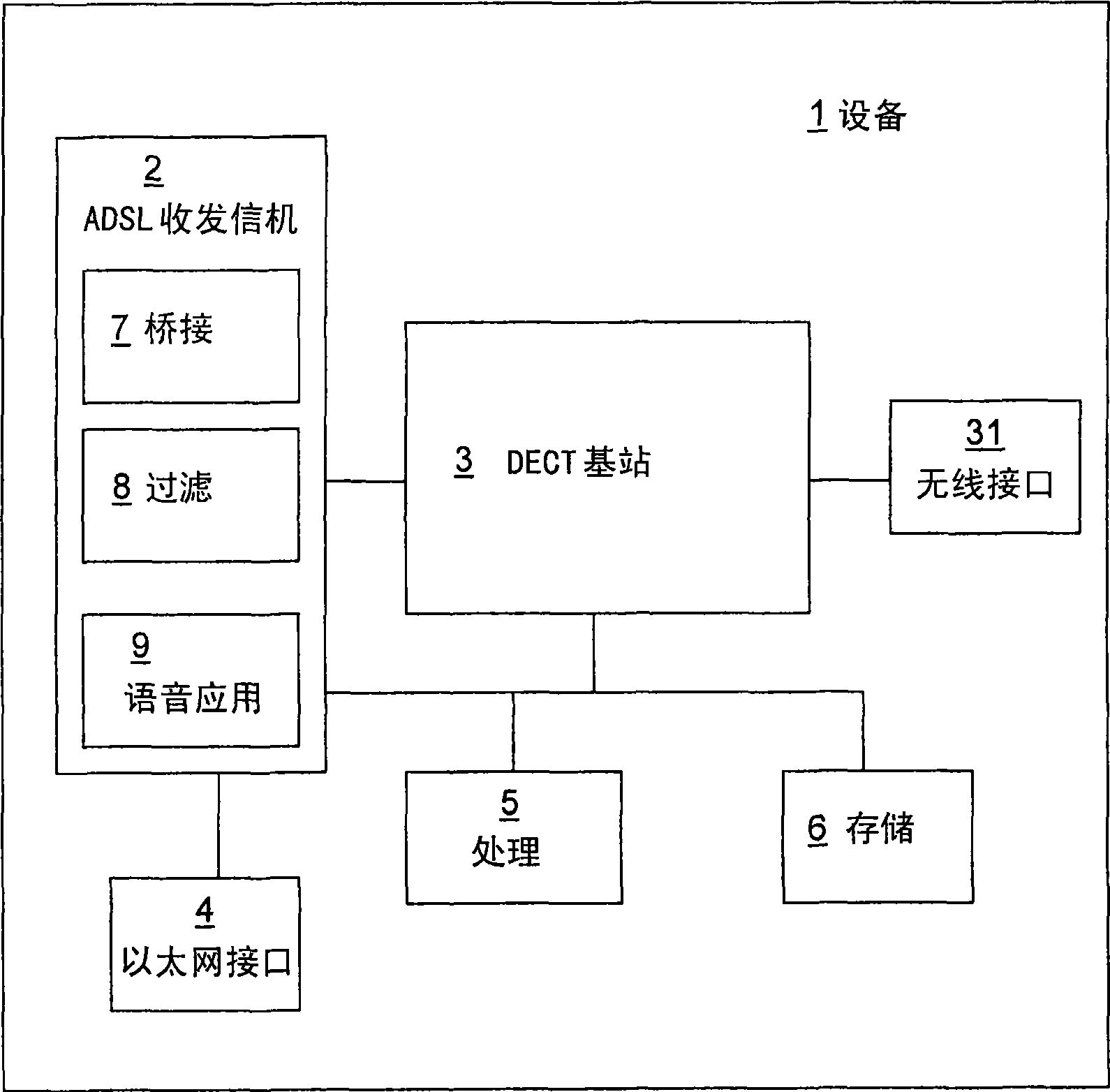
[0025] exist figure 2 In , the represented block diagrams are merely functional entities and do not necessarily have to correspond to physically separate entities. That is, these functional entities may be developed in software or implemented in one or more integrated circuits.

[0026] The example embodiments pertain to the SIP and DECT frameworks, but are not limited to this specific environment, and can also be applied in other frameworks where terminals on one network access services on another network.

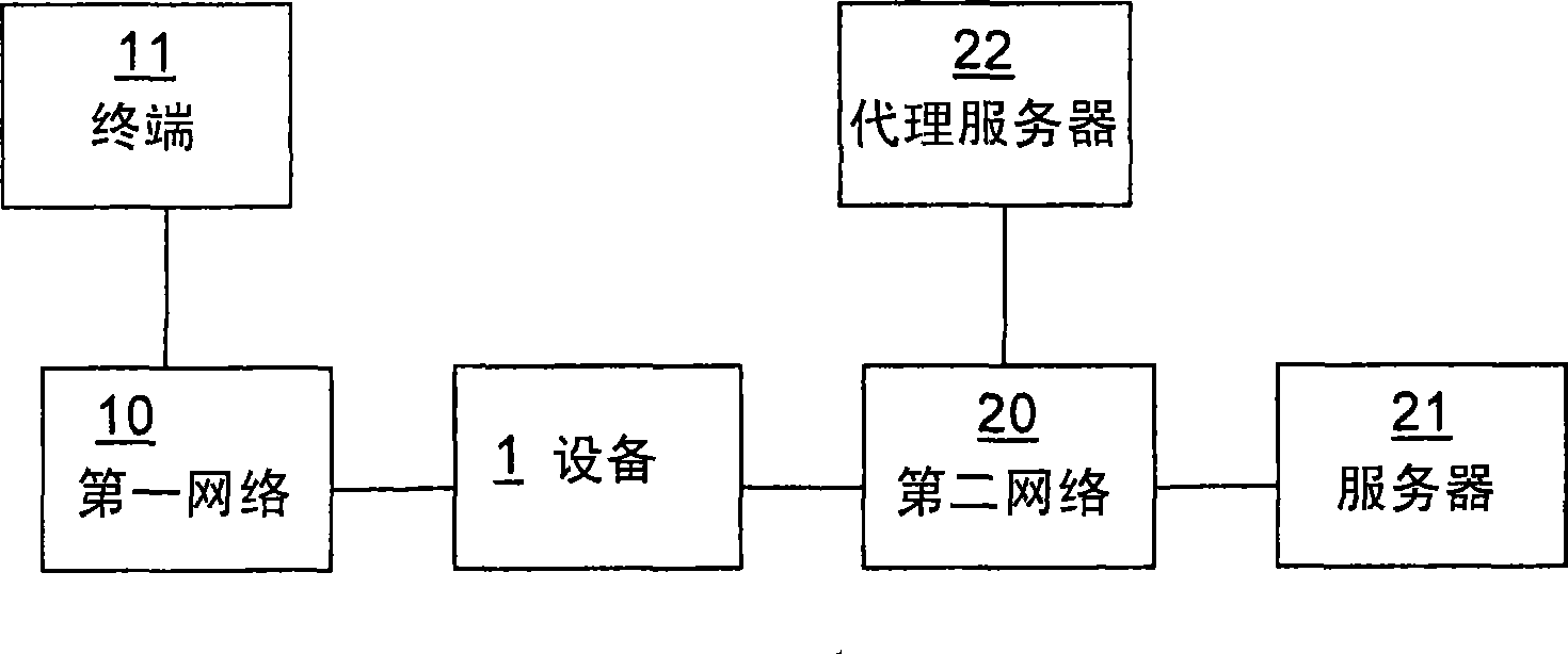
[0027] figure 1 Representing a device 1 of an embodiment, the device 1 is a customer premises equipment (denoted CPE), hereinafter also referred to as a gateway. The CPE comprises an interface to a first network, which is a DECT network. The first network comprises at least a DECT terminal 11 associated with a DECT base station comprised in a CPE. Of course, the first network may be another type of local network (wired or wireless) with devices supporting voice servi...


PUM


Abstract

The present invention concerns a networking device (1) comprising a first interface to a first network (10) and a second interface to a second network (20). The device comprises connecting means (3) for associating to a terminal (11) located on the first network and storing a unique and permanent identifier of the terminal, means (9) for registering with an address comprising the terminal identifier to a server located on the second network for using a service, and means (7) for enabling the terminal to use the service on the address.

Description

technical field [0001] The invention relates to a device and a method for realizing the mobility of a SIP DECT terminal. Background technique [0002] Many applications on the Internet require the creation and management of sessions, where a session is an exchange of data between groups of participants. The Session Initiation Protocol, denoted SIP, is defined in Internet Engineering Task Force IETF's Request for Comments Standard Number RFC3261. SIP is an application-layer control protocol for creating, modifying, and terminating sessions with one or more participants. These sessions include: Internet telephony calls, multimedia distribution, and multimedia conferences. SIP invites are used to create a session and carry a session description that enables participants to agree on a set of compatible media types. [0003] SIP enables Internet endpoints (also called user agents (agents), denoted SIP UAs) to discover each other and agree on the characteristics of the sessions...

Claims


Application Information

Patent Timeline
Patent Type & Authority Applications(China)
IPC IPC(8): H04M7/00H04L29/06
CPCH04L29/06326H04M1/725H04L29/06238H04L29/06258H04M2250/08H04M1/2535H04L65/1036H04L65/1026H04L65/1069H04L29/06027H04M7/00H04L65/1101
Inventor 米克·德凯泽吕克·吉森林克
Owner THOMSON LICENSING SA
Why Eureka
Try Eureka