Electric lifting device

An electric hoisting device and electric technology, applied in cranes and other directions, can solve problems such as hidden safety hazards, inconvenient loading and unloading operations, and difficult telescopic operations, and achieve the effects of saving manpower, improving loading and unloading accuracy and work efficiency

Inactive Publication Date: 2009-08-19
NINGBO ELEVATOR WINCH MFG
View PDF0 Cites 9 Cited by
  • Summary
  • Abstract
  • Description
  • Claims
  • Application Information

AI Technical Summary

Problems solved by technology

Due to the fact that users have higher and higher requirements for the lifting height, when telescopic, they often have to stand very high to pull out the telescopic arm by hand, which is not only troublesome, but also has potential safety hazards; moreover, it is difficult to stretch after lifting the goods Operation, inconvenient for difficult loading and unloading operations

Method used


Image

  • Electric lifting device
  • Electric lifting device
  • Electric lifting device

Examples


Embodiment Construction

[0018] The present invention will be further described in detail below in conjunction with the accompanying drawings and specific embodiments.

[0019] Such as figure 1 , figure 2 , image 3 , Figure 4 shown.

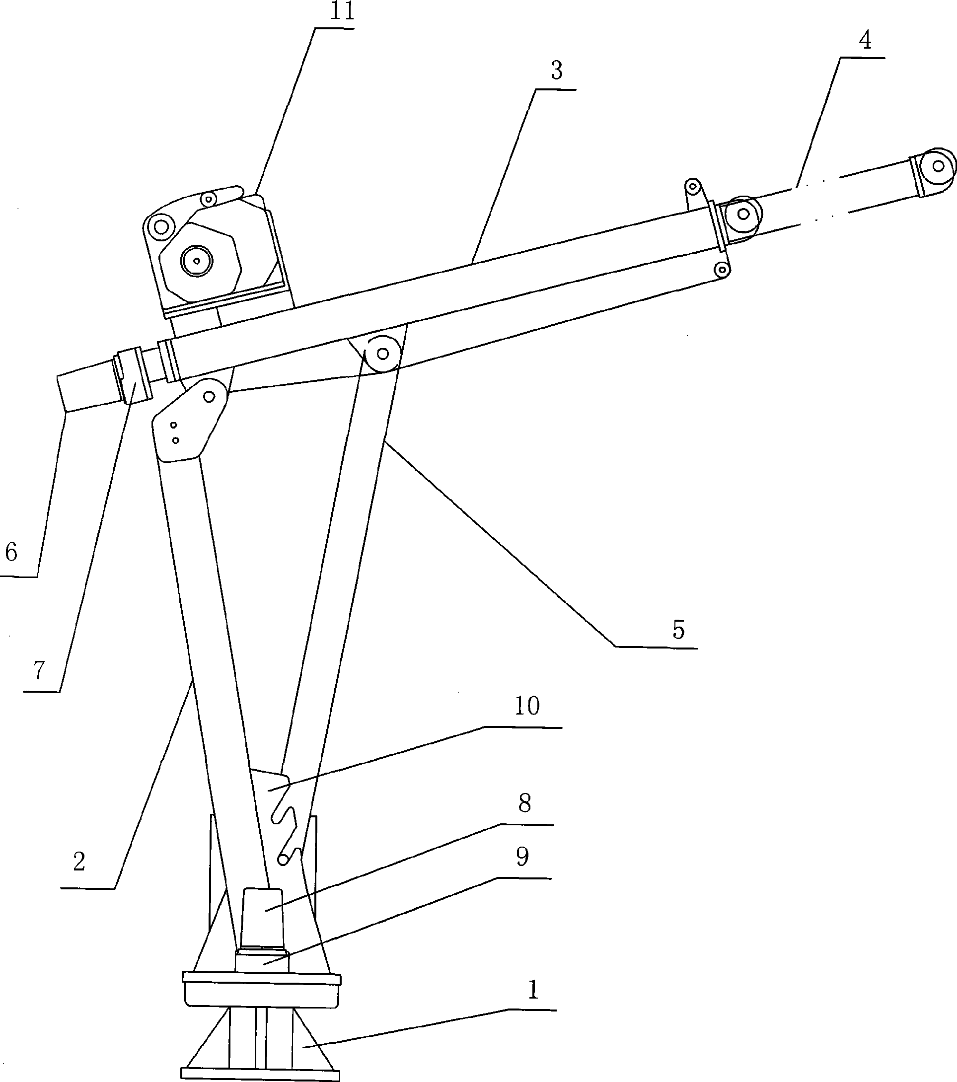
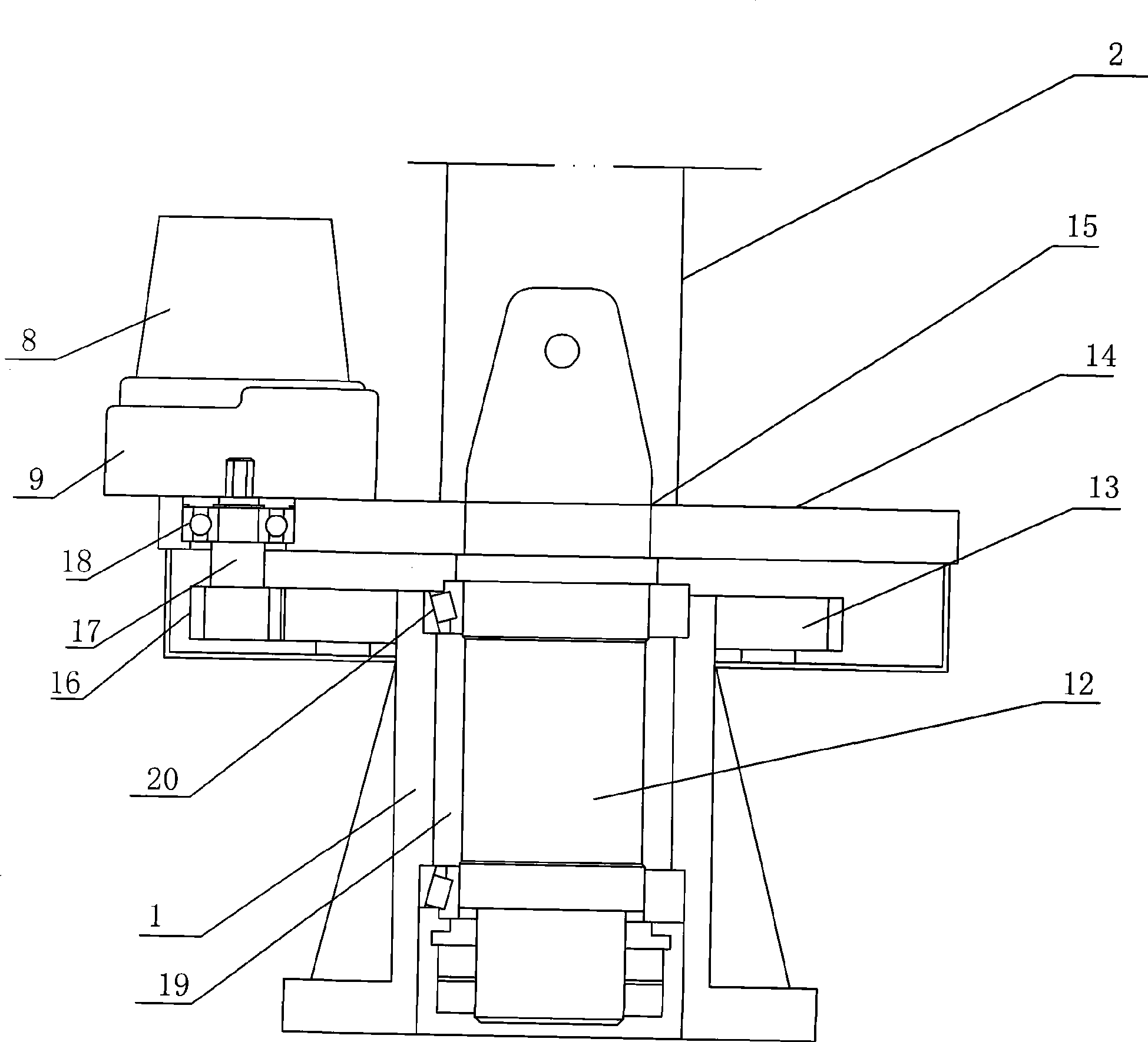
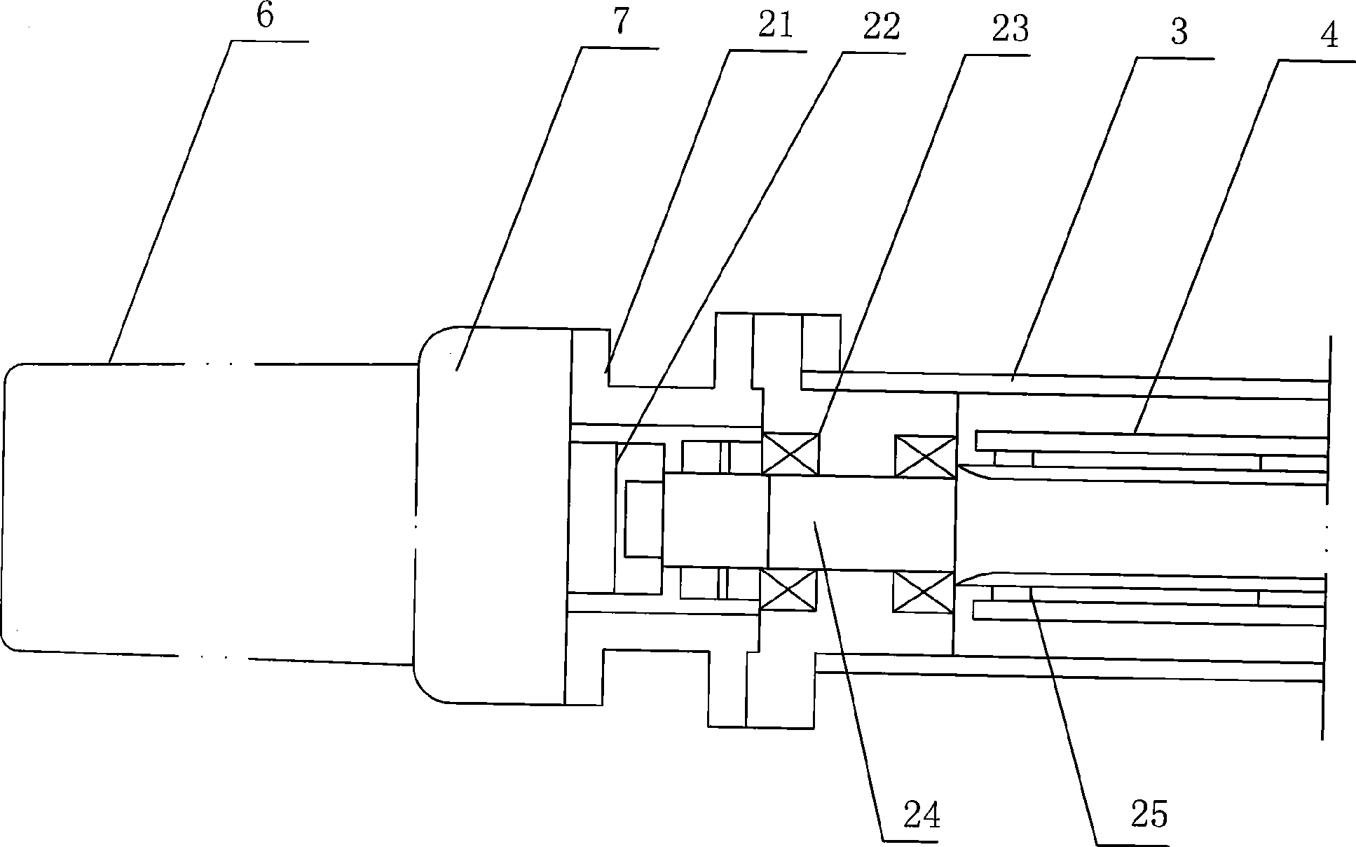
[0020] The electric lifting device of the present invention includes a base 1, a main arm 2, a cross arm 3, a lifting mechanism 11, a telescopic arm 4, and a rotating main shaft 12. The lifting mechanism 11 is installed on the cross arm 3, and the rotating main shaft 12 The lower part of the base 1 rotates and fits with the central hole I19 of the base 1, and the telescopic arm 4 slides and fits in the cross arm 3. An electric rotating mechanism is arranged between the base 1 and the main arm 2, and the electric rotating mechanism Including drive motor I8, speed reducer I9, drive gear 16, rotating disk 14 and ring gear 13 fixedly connected with the outer wall of center hole I19 of base 1, the output shaft end of said drive motor I8 is connected with speed reducer ...


PUM


Abstract

The invention discloses an electric hoisting device, which comprises a substrate, a main arm, a cross arm, a hoisting mechanism, a telescopic arm and a rotating main shaft, wherein an electric rotating mechanism is arranged between the substrate and the main arm; the electric rotating mechanism comprises a driving motor I, a speed reducer I, a driving gear, a rotating disk and a gear ring which is fixedly connected with the outer wall of a center hole I of the substrate, the output shaft end of the driving motor I is connected with the speed reducer I, the speed reducer I is fixedly connected with the rotating disk, the lower end of an output shaft of the speed reducer I is fixedly connected with the driving gear, and the driving gear is meshed with the gear ring; and the rotating main shaft is fixedly connected with a center hole II of the rotating disk, and the lower end of the main arm is fixedly connected with the upper end face of the rotating disk. The electric hoisting device can make the main arm automatically rotate and can control the position in real time. The electric hoisting device also comprises an electric telescopic mechanism which can operate the flexibility of the telescopic arm to carry out charging and discharging operation on goods with high difficulty and accurate position according to the distance for charging and discharging the goods.

Description

technical field [0001] The invention relates to the field of cargo lifting devices, in particular to an electric lifting device. Background technique [0002] At present, the electric lifting device is mainly used for loading and unloading goods on miniature or light trucks or loading and unloading goods on the job site. Its structure mainly includes main arms, cross arms, bases, and lifting devices. , There is a rotating mechanism and a rotating main shaft in the rotating mechanism between the main arm and the base, and the lifting device is arranged on the cross arm. The rotation of its rotary mechanism of the above-mentioned electric lifting device is controlled by manpower. Its rotating mechanism is that the bottom of the rotating main shaft and the base pass through a combination of a ball bearing and a plane bearing or a combination of a shaft sleeve and a plane bearing, and then the rotation is completed by the promotion of manpower. However, in the case of heavy li...

Claims


Application Information

Patent Timeline
Patent Type & Authority Applications(China)
IPC IPC(8): B66C23/04B66C23/06B66C23/687B66C23/62
Inventor 程继红
Owner NINGBO ELEVATOR WINCH MFG
Why Eureka
Try Eureka