Large-caliber pneumatic multi-way eccentric butterfly valve

An eccentric butterfly valve, large-diameter technology, used in multi-way valves, valve details, valve devices, etc., can solve the problems of large valve stem rotation resistance, slippage, difficulty in meeting sealing and valve disc movement, etc., to improve operational flexibility, Simple operation and improved bonding effect

Active Publication Date: 2019-02-15
FUJIAN FEIDA VALVE TECH CO LTD
View PDF10 Cites 0 Cited by
  • Summary
  • Abstract
  • Description
  • Claims
  • Application Information

AI Technical Summary

Problems solved by technology

This technical solution has the following technical defects: the two butterfly valves do not produce a linkage effect in essence, and belong to the simple superposition of two independent valve structures, which does not bring outstanding performance in terms of equipment operation and equipment structure optimization. The improvement effect of
This technical solution has the following technical defects: the hinged way can achieve the technical effect of one of the valve clacks being opened, the other valve clack being closed, or both valve clacks being opened at a certain angle at the same time, but it is not possible to individually target one of the valve clacks. In other words, in order to meet the tightness of the valve, there are multiple sealing structures at the connection between the valve stem and the valve body, which leads to the valve stem The rotation resistance is relatively large, and the hinged transmission mode acts on the valve technical field. The torsion force of the connecting rod acts on the valve stem, which is prone to technical problems of relative slipping and affects the normal operation of the valve.
Since the valve stem in this technical solution must be set at the center, the eccentric setting of the butterfly valve cannot be realized, and it is difficult to meet the requirements of sealing and disc movement

Method used


Image

  • Large-caliber pneumatic multi-way eccentric butterfly valve
  • Large-caliber pneumatic multi-way eccentric butterfly valve
  • Large-caliber pneumatic multi-way eccentric butterfly valve

Examples


Embodiment 1

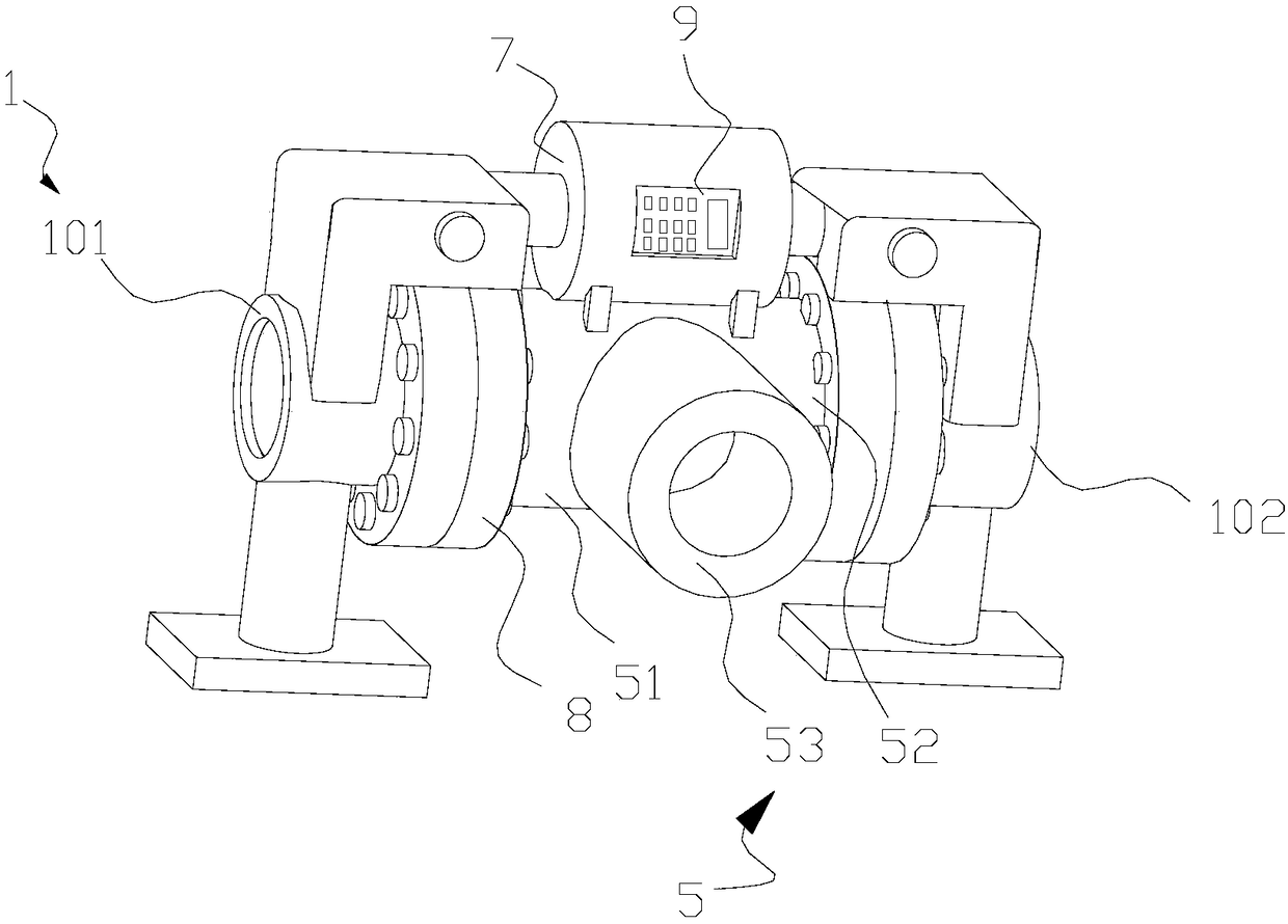
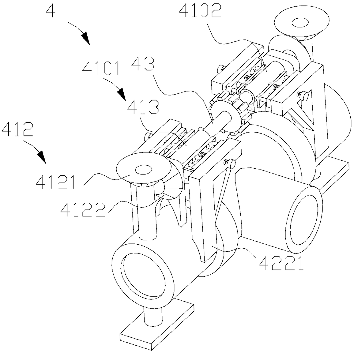
[0042] Such as figure 1 , 2 , 7, this embodiment discloses a large-diameter pneumatic multi-way eccentric butterfly valve, including a butterfly valve body 1, a pneumatic device, a tee pipe 5, and a sliding connection transmission device 4. Such as Figure 7 , 8 As shown, the butterfly valve body 1 includes a valve body 11, a valve stem 12, a valve seat, and a valve disc 14. The valve stem 12 runs through the valve body 11, and the valve disc 14 is installed on the valve stem 12 and is limited in the cavity of the valve body 11. , The valve seat is fitted on the inner wall of the valve body 11 . A butterfly valve body 1 is respectively connected to two horizontally connected ports in the three-way pipe 5 , which are referred to as the first butterfly valve body 101 and the second butterfly valve body 102 in this embodiment. Such as Figure 3-5 As shown, the sliding connection transmission device 4 includes a fixed transmission assembly 41, a push-type positioning device 4...

Embodiment 2

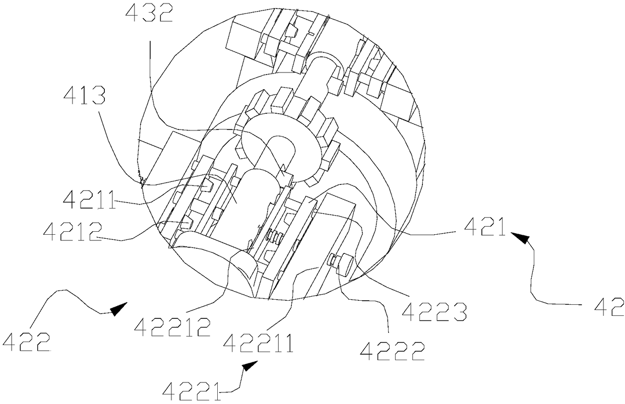
[0049] Such as figure 2 , 3 , 4, the difference between this embodiment and the above-mentioned embodiments is that the pushing device 422 includes a bracket 4221, a guide rail 4222, and a screw rod 4223, the bracket 4221 is installed on the valve body 11, and the bracket 4221 includes a first support rod 42211, a second The support rod 42212, the first support rod 42211, and the second support rod 42212 are parallel to each other, and the second support rod 42212 is close to the fixed guide rotating cylinder 413, and the first support rod 42211 is away from the fixed guide rotating cylinder 413, on the second support rod 42212 A first through hole (not shown in the figure) and a second through hole (not shown in the figure) corresponding to the first through hole 4131101 and the second through hole 4131102 are provided. The guide rail 4222 and the screw rod 4223 are connected in parallel between the first support rod 42211 and the second support rod 42212, wherein one end o...

Embodiment 3

[0053] Such as figure 1 , 2 , 3, the difference between this embodiment and the above-mentioned embodiments is that the pushing device 422 includes a bracket 4221 and a push cylinder (not shown in the figure), the bracket 4221 is installed on the valve body 11, and the cylinder end of the push cylinder is connected to the bracket 4221 connection, the piston rod end of the push cylinder is connected with the pressing plate 421, and the piston rod end of the push cylinder is elongated to drive the protrusion to be inserted into the corresponding through hole 41311.

[0054] The push cylinder of the present invention is preferably a servo push cylinder, and the elongation movement of the piston rod end drives the pressing plate 421 close to the fixed guide rotating cylinder 413, thereby realizing that the first protrusion 4211 and the second protrusion 4212 respectively extend into the corresponding first channel. In the hole 4131101 and the second through hole 4131102; the pist...


PUM


Abstract

The invention discloses a large-caliber pneumatic multi-way eccentric butterfly valve. The large-caliber pneumatic multi-way eccentric butterfly valve comprises two butterfly valve bodies, a three-waypipe and a slip connection-type transmission device; two interfaces communicating horizontally in the three-way pipe are connected with the two butterfly valve bodies correspondingly; the slip connection-type transmission device comprises two sets of fixed transmission assemblies, push-type positioning devices and a movable connecting piece; the two sets of fixed transmission assemblies are arranged on the corresponding butterfly valve bodies in manner of mirror symmetry; each set of fixed transmission assemblies comprises a reversing device and a fixed guide rotating tube; each fixed guide rotating tube is connected with a valve rod through the corresponding reversing device; protrusions in each pressing plate can be driven by movement of a corresponding push device to be inserted into through holes of a corresponding guide rotating tube correspondingly; each of the end parts of the movable connecting piece is provided with elastic pieces corresponding to the through holes on a one-to-one basis; the end parts of the elastic pieces can extend out of the corresponding through holes; and a pneumatic device is used for driving the movable connecting piece to rotate. The large-caliberpneumatic multi-way eccentric butterfly valve disclosed by the invention has the advantages that not only can all the valve bodies be regulated alone but also linkage regulation can be performed on the two valve bodies.

Description

technical field [0001] The invention relates to the technical field of butterfly valves, in particular to a large-diameter pneumatic multi-way eccentric butterfly valve. Background technique [0002] Butterfly valve, also known as flap valve, is a regulating valve that can be used for switch control of low-pressure pipeline media. Butterfly valves are divided according to the driving mode: electric butterfly valve, pneumatic butterfly valve, hydraulic butterfly valve, manual butterfly valve, according to the structural form: central sealing butterfly valve, single eccentric sealing butterfly valve, double eccentric sealing butterfly valve, triple eccentric sealing butterfly valve, etc. [0003] The pneumatic butterfly valve mainly drives the valve stem to rotate by starting the piston rod movement in the actuator to realize the opening or closing of the valve disc. The single eccentric butterfly valve is to solve the extrusion problem of the butterfly plate and the valve se...

Claims


Application Information

Patent Timeline
Patent Type & Authority Applications(China)
IPC IPC(8): F16K11/052F16K31/16
CPCF16K11/052F16K31/1635Y02T10/12
Inventor 夏传虎汪宇程梁世耿李泉水
Owner FUJIAN FEIDA VALVE TECH CO LTD
Why Eureka
Try Eureka