LED and relevant backlight module

A technology of light emitting diodes and backlight modules, which is applied to optical elements, optics, light sources and other directions used to change the spectral characteristics of emitted light, can solve problems such as uneven brightness, insufficient brightness, and increased cost, and achieve large design flexibility, extreme Competitive, low module cost effects

Inactive Publication Date: 2009-08-19
LITE ON OPTO TECH (CHANGZHOU) CO LTD +2
View PDF5 Cites 12 Cited by
  • Summary
  • Abstract
  • Description
  • Claims
  • Application Information

AI Technical Summary

Problems solved by technology

However, the control of the lateral light intensity and lateral angle of the above-mentioned LEDs is not ideal. Therefore, when the LEDs are to form a backlight module, the array spacing of the LEDs is also limited within a certain distance to avoid problems such as insufficient brightness and uneven brightness. However, such a solution results in an increase in the number of LEDs and an increase in cost

Method used


Image

  • LED and relevant backlight module
  • LED and relevant backlight module
  • LED and relevant backlight module

Examples


Embodiment Construction

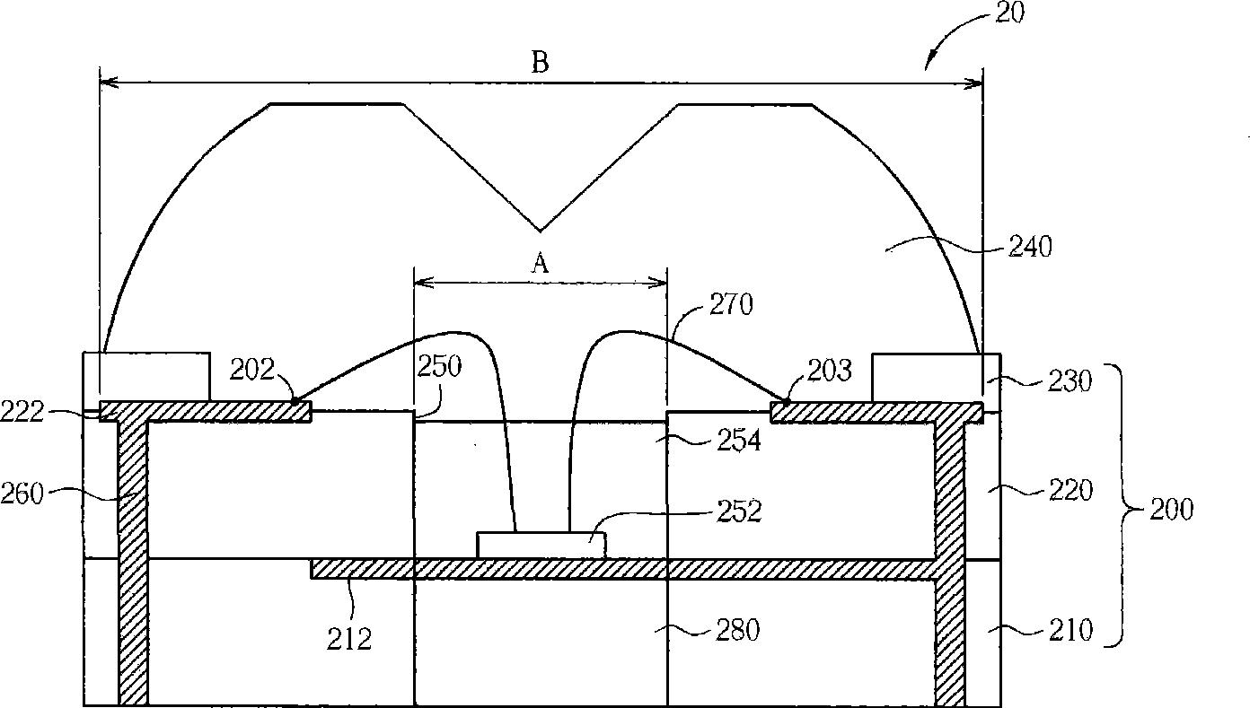
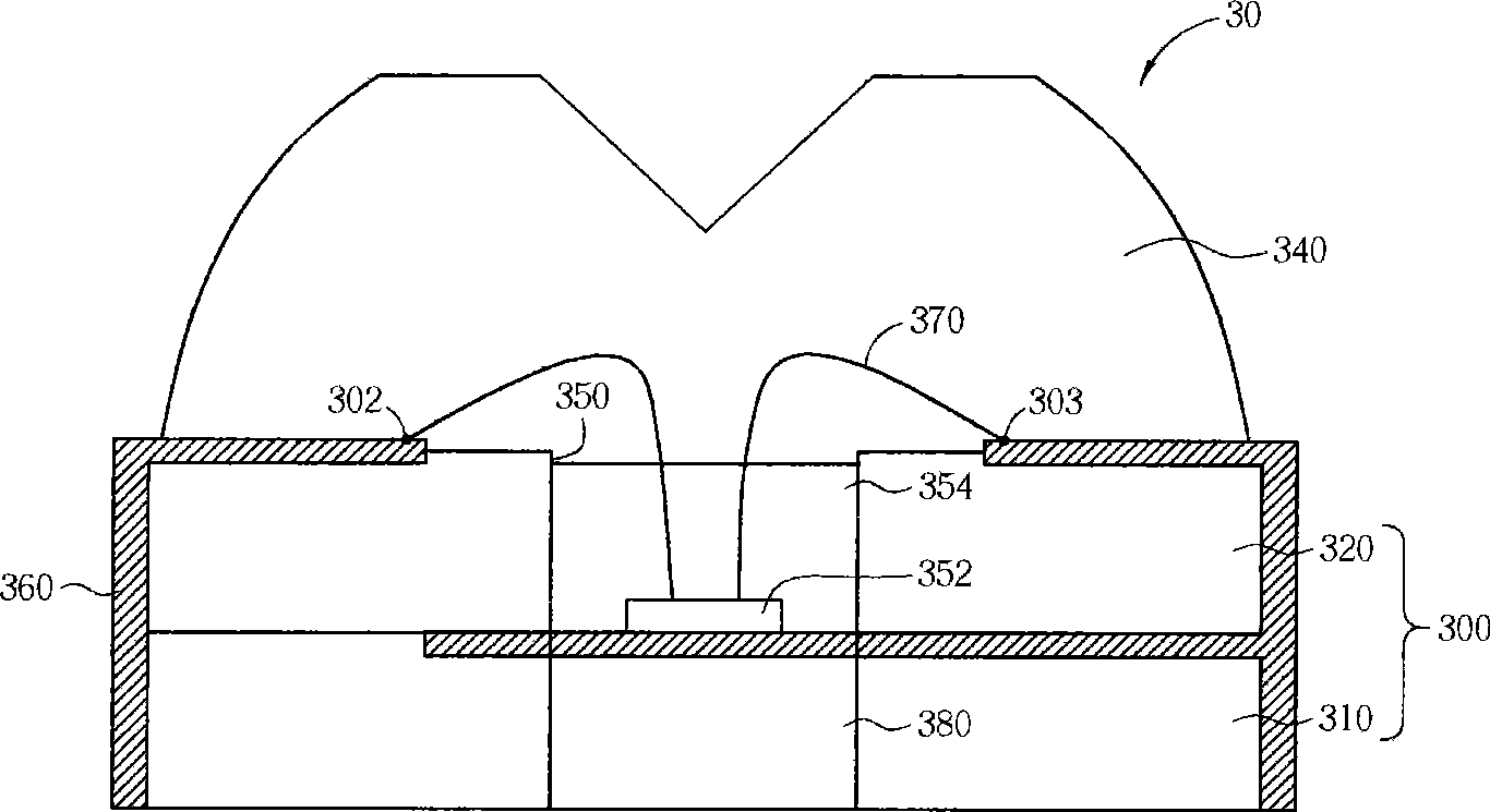
[0045] Please refer to figure 2 , image 3 . The light emitting diode 20, 30 of the present invention comprises a base structure 200, 300, a light emitting diode chip 252, 352, a phosphor layer 254, 354 and a lens (lens) 240, 340, wherein the base structure 200, 300 has a groove 250, 350, the light-emitting diode chip 252, 352 can be placed therein, and the phosphor layer 254, 354 is arranged in the groove 250 and covers the light-emitting diode chip 252, 352, in order to convert the chip light emission wavelength into other light emission wavelength and increase the light color uniformity of the light emitting diodes 20, 30, the lens 240, 340 is arranged on the base structure 200, 300, in order to adjust the light emitted by the light emitting diode chip 252, change its luminous field shape, and the base structure 200 , 300 further includes at least one conductive terminal 202 , 203 , 302 , 303 for providing the voltage required for the LED chip 252 , 352 to emit light.

...


PUM


Abstract

The invention provides a light-emitting diode which comprises a light-emitting diode chip, a substrate structure, a fluorescent powder layer and a lens, wherein the substrate structure is provided with a concaved groove so that the light-emitting diode chip and the fluorescent powder layer can be arranged in the concaved groove at the same time; the lens is arranged on the substrate structure and provided with a curve side wall, the top of the lens is provided with a flat panel and an inverted cone-structure female cone is arranged in the center of the top.

Description

technical field [0001] The invention provides a light-emitting diode and its related backlight module, especially a light-emitting diode with a lens (lens), so that the light-emitting diode has a side light field and a related backlight module. Background technique [0002] In recent years, the application fields of light emitting diodes (hereinafter referred to as LED (light emitting diode)) have been continuously developed. LED is cold light emitting, which has the advantages of low power consumption, long component life, no need to warm up the lamp time, and fast response speed. In addition, it is small in size, resistant to vibration, suitable for mass production, and can be easily made into a very small or Advantages such as array-style components. Light-emitting diode (LED) devices often need to match the beam pattern, view angle, or light output angle in order to meet the requirements of the application; therefore, when the LEDs are arranged in a matrix, it is necess...

Claims


Application Information

Patent Timeline
Patent Type & Authority Applications(China)
IPC IPC(8): H01L33/00F21V9/10F21V5/04F21Y101/02F21V9/40
CPCH01L33/58G02B19/0061G02F1/133603G02B19/0028G02B27/0955G02B27/0916H01L33/483H01L33/62H01L2924/0002H01L2224/48091H01L2924/00014H01L2924/00
Inventor 高志强周孟松王修辞林贞秀吴嘉豪
Owner LITE ON OPTO TECH (CHANGZHOU) CO LTD
Why Eureka
Try Eureka