Eureka AIR delivers breakthrough ideas for toughest innovation challenges, trusted by R&D personnel around the world.

Overhead network barrier-clearance and detection robot

An overhead line and robot technology, applied in the direction of manipulators, manufacturing tools, etc., can solve the problems of no automatic obstacle clearance, high labor intensity, low efficiency, etc., and achieve the effect of convenient long-distance control, improved work efficiency, and low manufacturing cost.

Inactive Publication Date: 2009-08-26
STATE GRID SHANDONG ELECTRIC POWER +1
View PDF0 Cites 19 Cited by
  • Summary
  • Abstract
  • Description
  • Claims
  • Application Information

AI Technical Summary

Problems solved by technology

[0002] Overhead lines, especially ultra-high-voltage lines, have been in the wild for a long time. Foreign objects such as kites, plastic greenhouse tarpaulins, and plastic mulches that endanger the operation of transmission lines are often suspended on ultra-high-voltage lines. If they are not cleaned up in time, it will easily affect the normal transmission of power.
At present, the removal of foreign objects suspended on overhead lines is mainly done manually, that is, the location of foreign objects is determined by visual inspection or observation with the help of telescopes, and then the staff work at heights to remove foreign objects; however, the above methods are labor intensive and dangerous for working at heights. High and low efficiency defects, it is difficult to achieve the desired result
Although there are intelligent robots that can walk on overhead lines and detect in real time, such robots can only walk on a single overhead line at present, and cannot travel across spacers on multiple wires such as 500kV overhead lines; Some robots are only used for line inspection, do not have the function of automatic obstacle removal, and cannot replace personnel to work well

Method used


Image

  • Overhead network barrier-clearance and detection robot
  • Overhead network barrier-clearance and detection robot
  • Overhead network barrier-clearance and detection robot

Examples


Embodiment Construction

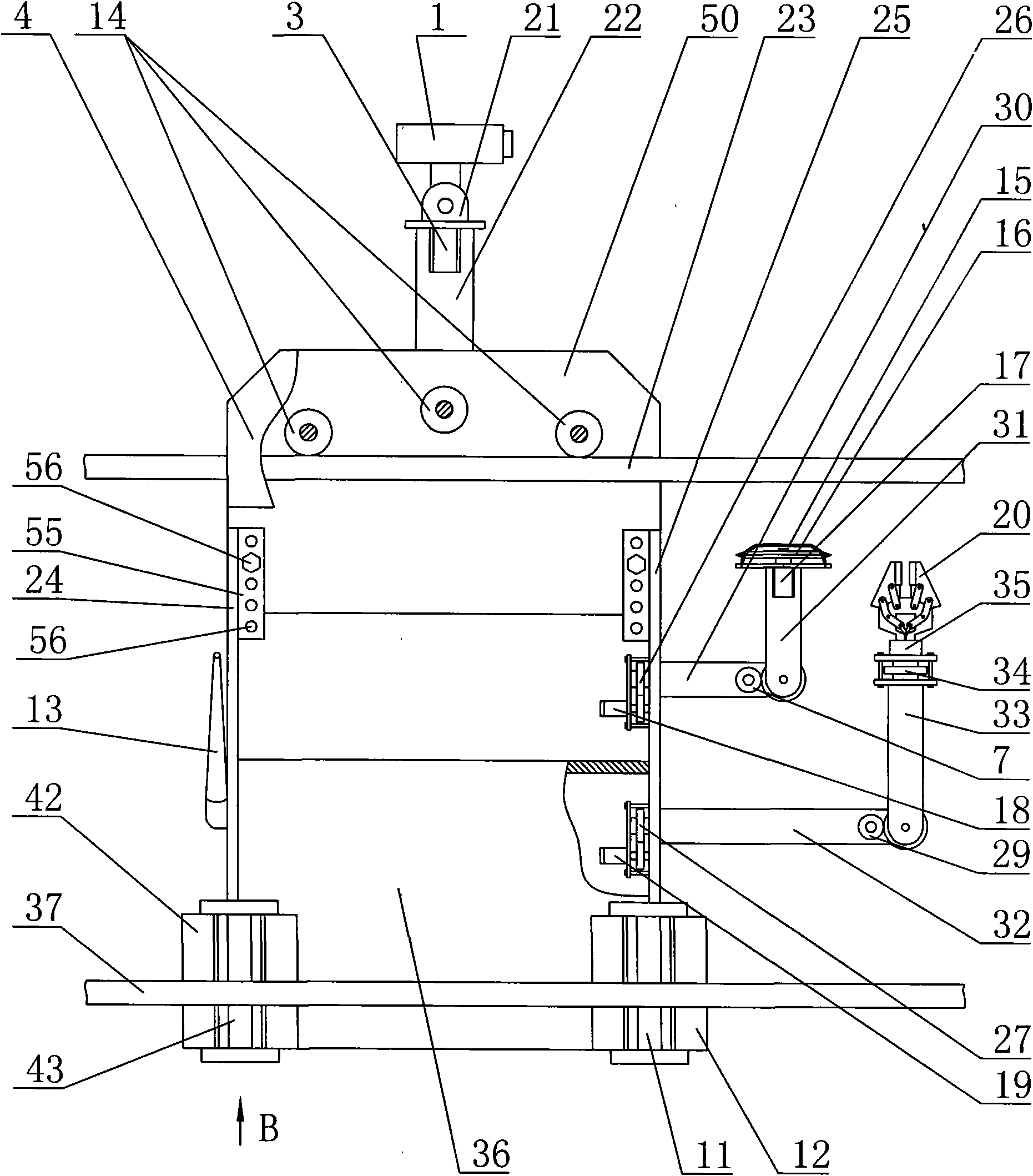
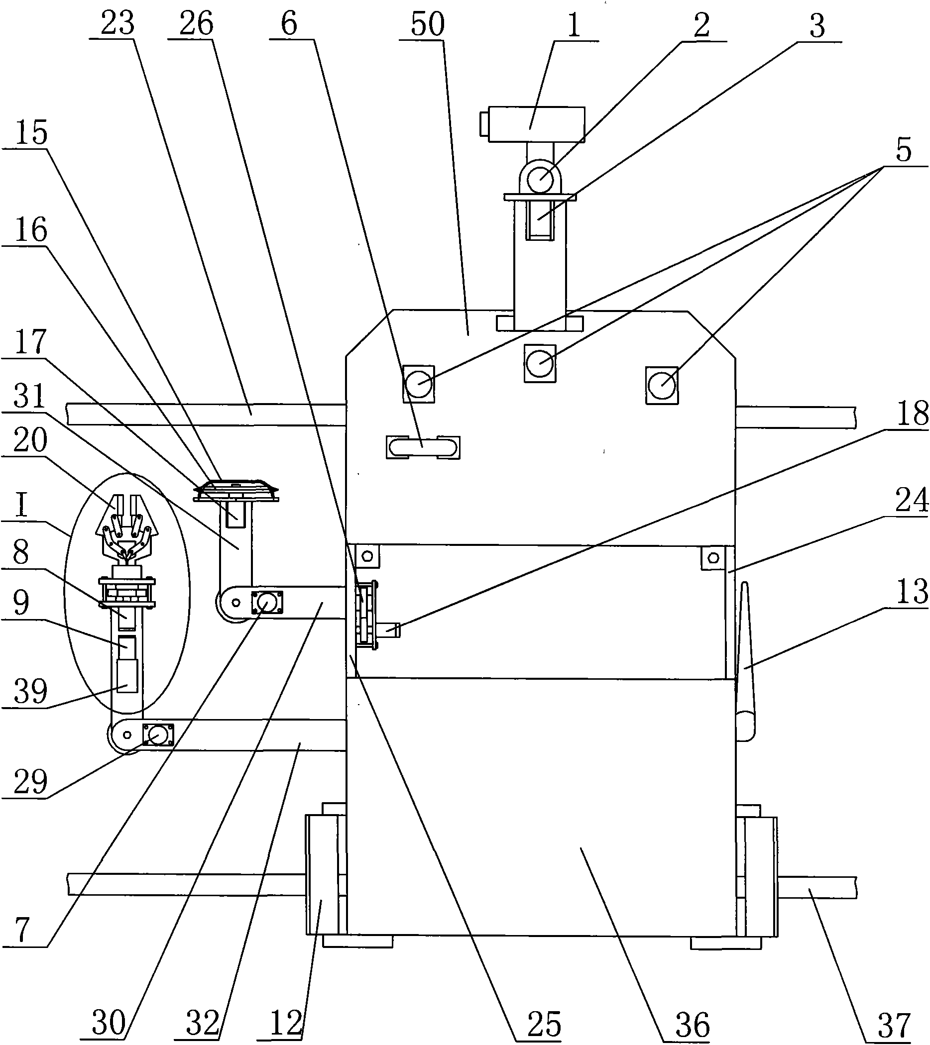
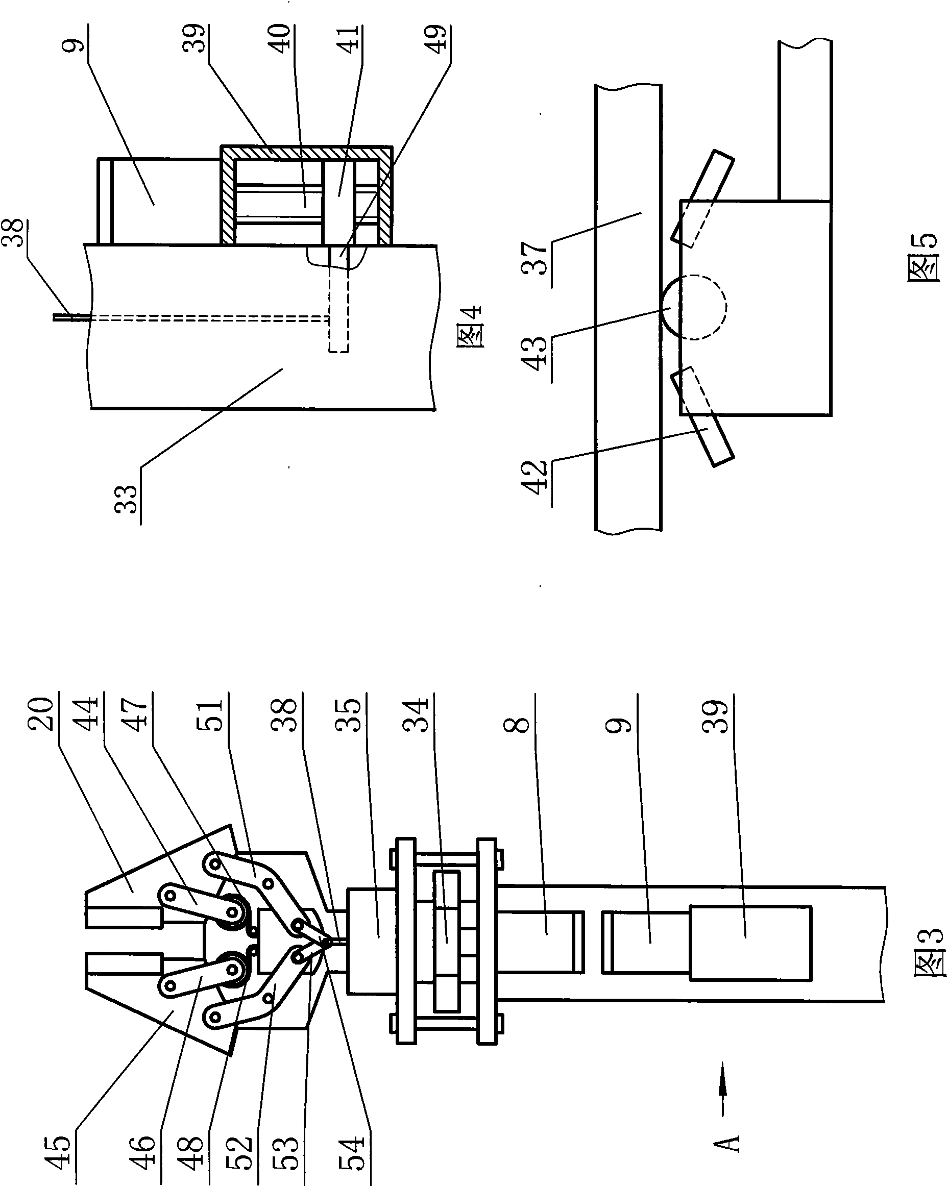
[0009] The overhead line obstacle removal detection robot of the present invention comprises an electrical box 36, and a first side plate 24 and a second side plate 25 are installed on the electrical box 36, and the first side plate 24 and the second side plate 25 are installed on the top of the first side plate. plate 50, the second mounting plate 4 is installed on the first mounting plate 50, the electrical box 36, the first side plate 24, the second side plate 25 and the first mounting plate 50 are connected to form a body, the body structure is simple, the volume is small, and the weight It is light, easy to install on overhead lines, and can minimize the impact of the robot on overhead lines; the second mounting plate 4 is separated from the first mounting plate 50 by a certain distance, and the second mounting plate 4 is equivalent to the suspension arm. Three drive wheels 14 are installed between the mounting plate 4 and the first mounting plate 50, three travel motors 5...


PUM


Abstract

The invention discloses an overhead network barrier-clearance and detection robot which comprises an electrical box which is equipped with two lateral plates. The upper part of the two lateral plates is equipped with a first mounting plate which is equipped with a second mounting plate. A driving wheel is installed between the first mounting plate and the second mounting plate. A travelling motor is installed on the first mounting plate and is connected with the driving wheel. A camera pole support is installed on the first mounting plate and is equipped with a second motor. An output shaft of the second motor is equipped with a camera base which is equipped with a first motor. The output shaft of the first motor is equipped with a camera. The second lateral plate is equipped with a mechanical arm. The overhead network barrier-clearance and detection robot can travel freely on a plurality of overhead networks with spacing rods and is not influenced by the spacing rods, and the overhead network barrier-clearance and detection robot can replace working personnel to carry out aloft work, clean up the sundries hung at the networks and ensure the normal operation of the network.

Description

technical field [0001] The invention relates to an overhead line obstacle removal detection robot. Background technique [0002] Overhead lines, especially ultra-high-voltage lines, have been in the wild for a long time. Foreign objects such as kites, plastic greenhouse tarpaulins, and plastic mulches that endanger the operation of transmission lines are often suspended on ultra-high-voltage lines. If they are not cleaned up in time, it will easily affect the normal transmission of power. . At present, the removal of foreign objects suspended on overhead lines is mainly done manually, that is, the location of foreign objects is determined by visual inspection or observation with the help of telescopes, and then the staff work at heights to remove foreign objects; however, the above methods are labor intensive and dangerous for working at heights. With high and low efficiency defects, it is difficult to achieve the desired result. Although there are intelligent robots that ...

Claims


Application Information

Patent Timeline
Patent Type & Authority Applications(China)
IPC IPC(8): B25J1/00
Inventor 苏建军刘洪正袁广宏朱德袆张军高森王斌张天河冯迎春吕宁高翔乔耀华吕守国杨立超张钦广李岐马玮杰宋晓东刘矞高金福李成远
Owner STATE GRID SHANDONG ELECTRIC POWER
Why Eureka
Eureka Blog
Learn More