Transfer printing device for cold-transfer decorating machines

A cold transfer printing and cooling device technology, which is applied to printing machines, transfer printing, rotary printing machines, etc., can solve the problems of unstable printing pressure and short printing time, and achieve increased transfer printing time, long transfer printing time, Guarantee the effect of transfer printing quality

Active Publication Date: 2009-08-26
NEWTECH TEXTILE TECH DEV SHANGHAI
View PDF3 Cites 16 Cited by
  • Summary
  • Abstract
  • Description
  • Claims
  • Application Information

AI Technical Summary

Problems solved by technology

[0003] In order to solve the problems of short printing time and unstable printing pressure of the transfer device of the existing cold transfer printing machine

Method used


Image

  • Transfer printing device for cold-transfer decorating machines
  • Transfer printing device for cold-transfer decorating machines
  • Transfer printing device for cold-transfer decorating machines

Examples


Embodiment 1

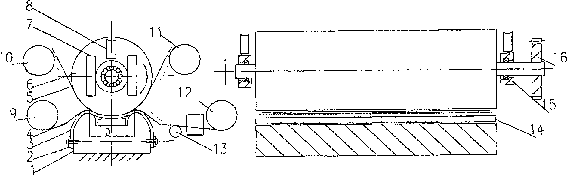
[0034] The transfer device of the cold transfer printing machine.

[0035] See figure 1 Shown: The transfer device of the cold transfer printing machine is located in the middle of the transfer printing machine, including mechanical parts such as the base, fixed splint, transfer belt, transfer roller, pressure device, cooling device, bearing seat and drive wheel. The transfer device of this cold transfer printing machine is composed of a transfer roller 6 , a transfer belt 3 , a cooling device 14 and a base 1 connected from top to bottom. In this embodiment, the base 1 is a one-piece concave rigid recess. Base 1 is fixed on the frame. The transfer roller 6 is a circular roller, the two ends of the central axis of the transfer roller are supported by bearings and bearing housings 15 and connected with the pressurizing device 8, and a cold transfer printing machine is installed next to the bearing at one end of the central axis. The transmission wheel 16 that transmission mec...

Embodiment 2

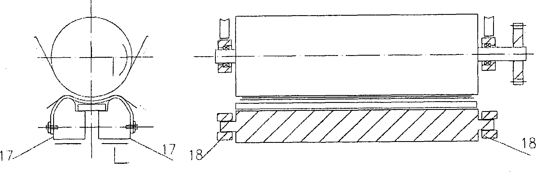
[0038] Transfer printing mechanism of variant A.

[0039] See figure 2 Shown: its principle and concrete implementation are identical except that base form is different, other structures are identical with embodiment 1. The difference is figure 1 Change the original transfer belt base 1 in figure 2 The two transfer belt installation bases 17, the base 17 can be moved on the sliding seat 18 and can be locked, the advantage of this is that the position of the transfer belt installation base 17 can be adjusted in the horizontal direction according to the needs, that is, the pressure can be adjusted. At the same time, the parallelism between the transfer belt 3 and the transfer roller 6 can also be adjusted, that is, the uniformity of the printing pressure can be adjusted. The advantage of the transfer printing mechanism of modification A is that it can not only adjust the pressure of the transfer roller on the transfer belt, but also adjust the size of the matching surface o...

Embodiment 3

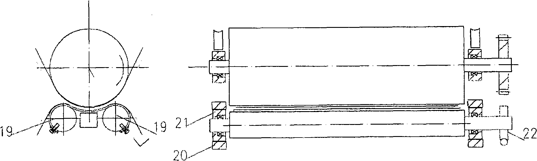
[0041] Transfer printing mechanism of variant B.

[0042] See image 3 Shown: its principle and concrete implementation are identical except that base is different, other structure is identical with embodiment 1. The difference is figure 1 The original transfer belt base 1 is changed into two transfer belt installation rollers 19, and the two ends of the transfer belt installation rollers 19 are equipped with bearings 21, bearing seats 20 and locking mechanisms 22 that can rotate and lock them. At least one transfer belt mounting roller 19 is rotatable. The advantage of this is that the locking mechanism can be opened as required and the transfer belt mounting roller 19 can be turned to adjust the length of the wrapping surface on the transfer belt 3 and the transfer roller 6, that is, adjust the size of the transfer printing area, and can also transfer at any time. Parallelism adjustment with 3 to ensure the uniformity of printing pressure. The advantage of the transfer p...


PUM


Abstract

The invention provides a transfer printing device for cold-transfer decorating machines, which comprises a base, a fixing clamp plate, a transfer printing belt, a transfer printing roller, a pressurization device, a bearing block and a driving wheel, wherein the transfer printing roller is a circular roller; two ends of a central shaft of the transfer printing roller are supported by a bearing and the bearing block and are connected with the pressurization device; the driving wheel connected with a drive mechanism is arranged beside the bearing at one end of the central shaft; the base is a concave rigid base fixed on a frame; the transfer printing belt is fixedly connected with the left and right sides of the concave rigid base by the fixing clamp plate; the transfer printing roller can rotate around the central shaft and move up and down relative to the transfer printing belt; and the acting surfaces of the transfer printing roller and the transfer printing belt fit each other, wherein the transfer printing belt stays still in a transfer printing process, and a cooling device is arranged between the transfer printing belt and the concave rigid base. As the transfer printing belt stays still, the transfer printing belt and the rotating transfer printing roller can form steady decorating pressure. Meanwhile, the flexibility of the transfer printing belt determines that a decorating area between the transfer printing belt and the transfer printing roller can be increased according to decorating requirements, thus enough transfer printing time required by a decorating process can be ensured.

Description

technical field [0001] The invention relates to printing and dyeing machinery in textile machinery, in particular to a transfer printing device of a cold transfer printing machine. According to the technical requirements of cold transfer printing, the transfer paper and the fabric to be printed are closely bonded, and the transfer printing device with the transfer roller and the transfer belt acting on the same surface, under certain pressure and time conditions, the dye pattern on the paper Transfer to fabric. Background technique [0002] The method of transfer printing was launched all over the world in 1968. Because the product and production process meet the requirements of energy saving and environmental protection, and the operation is simple, it quickly set off a revolution in the printing industry in the market. But this transfer printing is limited to synthetic fiber fabrics such as polyester fiber, and is applied to natural fiber fabrics such as cotton, wool and ...

Claims


Application Information

Patent Timeline
Patent Type & Authority Applications(China)
IPC IPC(8): B41F16/02B41F13/20B41F13/08
CPCD06B11/0076
Inventor 钟博文
Owner NEWTECH TEXTILE TECH DEV SHANGHAI
Why Eureka
Try Eureka