Rotating machine, continuous winding coil, distributed winding stator and method for forming same

A technology of rotating electric machines and winding coils, applied in the shape/style/structure of winding conductors, electric components, manufacturing motor generators, etc., which can solve problems such as current density reduction

Active Publication Date: 2009-08-26
HITACHI LTD
View PDF4 Cites 18 Cited by
  • Summary
  • Abstract
  • Description
  • Claims
  • Application Information

AI Technical Summary

Problems solved by technology

It is a problem to reduce the current density by making the conductor arranged in the groove finely divided in the radial direction.

Method used


Image

  • Rotating machine, continuous winding coil, distributed winding stator and method for forming same
  • Rotating machine, continuous winding coil, distributed winding stator and method for forming same
  • Rotating machine, continuous winding coil, distributed winding stator and method for forming same

Examples


Embodiment 1

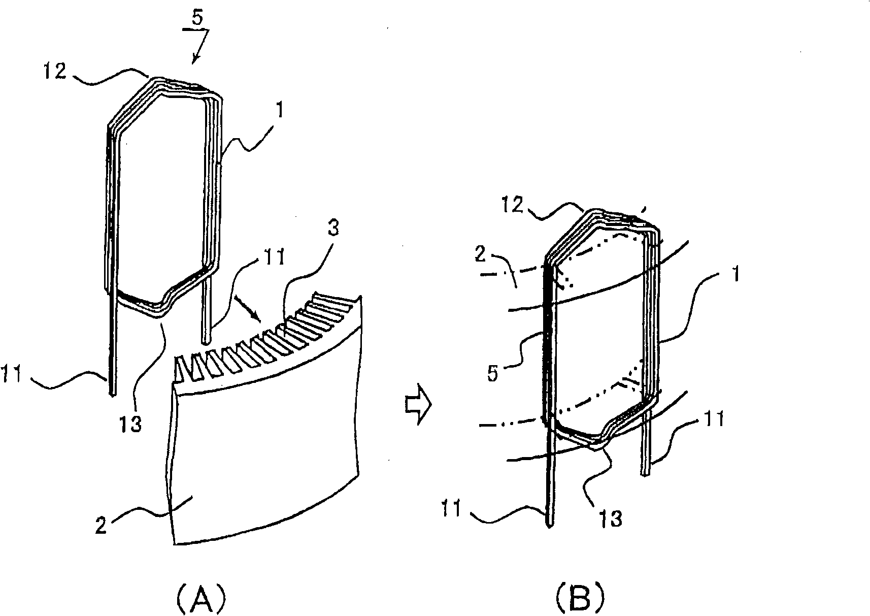
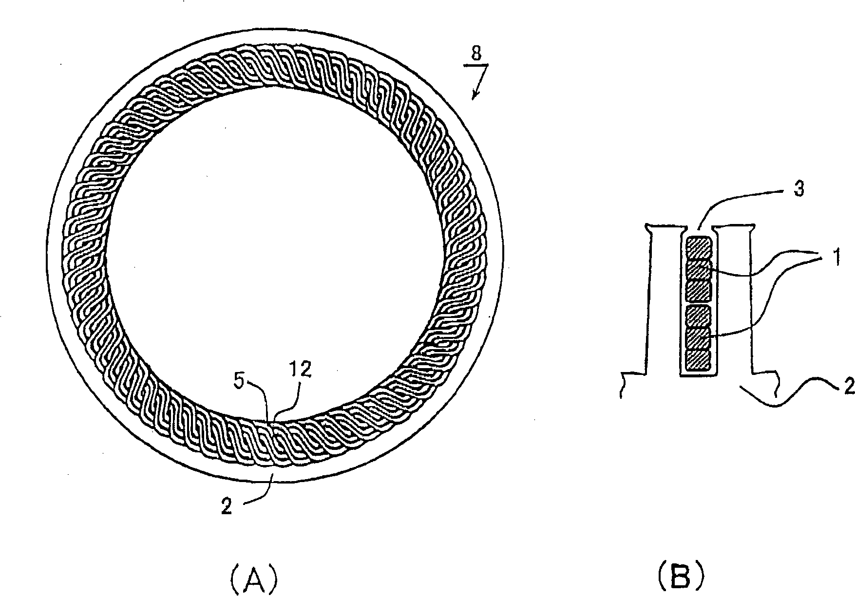
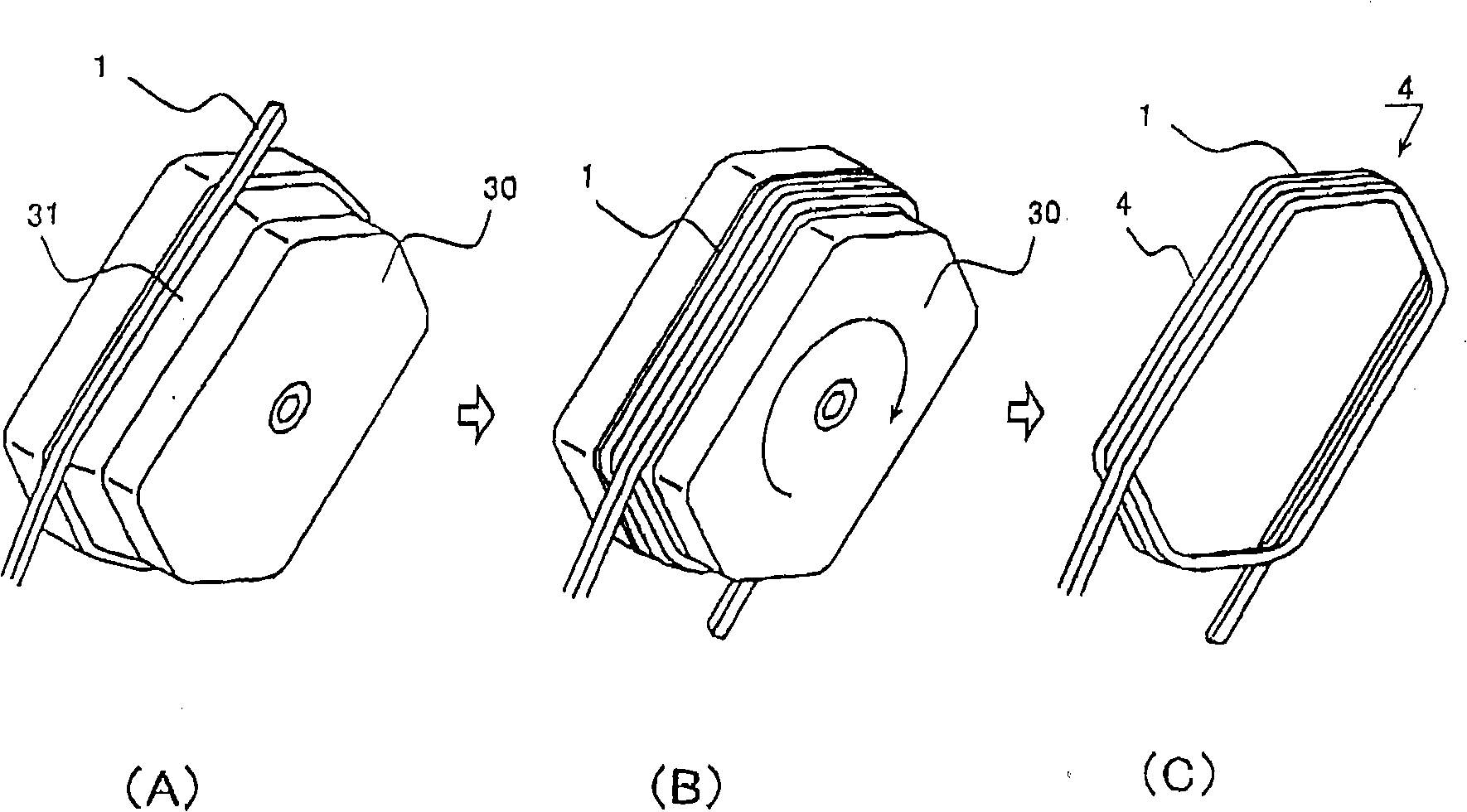
[0032] figure 1 The form-wound coil type structure of Example 1 of the present invention is shown. figure 1 (A) is a perspective view before the form-wound coil 5 is incorporated into the stator core 2, and the stator core 2 is cut and shown. figure 1 (B) is a perspective view showing a state where the form-wound coil 5 is incorporated into the stator core 2, and the outline of the stator core 2 is shown by a solid line and a two-dot chain line. The coil wire 1 is a copper corner wire covered with an enamel resin film. The stator core 2 is formed by press-cutting rolled steel plates with a thickness of about 1 mm and laminating them. Continuously wind the coil wire material 1 (three turns in the figure) of the corner wire with the same length or similar size on both sides, and place the top 12 and the coil end side of the coil wire material 1 that is overlapped and wound along the layer direction. The top portion 13 is bent into a crank shape to form a die-wound coil. The ...

Embodiment 2

[0052] Figure 12 A partial cross-sectional view showing a stator slot 3 in a state where form-wound coils are formed from corner wires 1 coated with thermal adhesive 14 and incorporated into stator core 2 according to Embodiment 2 of the present invention. Two corner wires 1 are bonded together to form roughly one corner wire, and form-wound coils are formed. The thermal adhesive 14 is melted by heating at a predetermined temperature. Two angled wires 1 are superimposed, and bonding can be performed by applying heating and cooling. This results in a structure in which twelve corner wires 1 are arranged in one groove. Therefore, the magnetic flux density is further increased, the current density is reduced, and the efficiency as a rotating electrical machine can be improved.


PUM


Abstract

The invention relates to a rotating machine, a crank-shaped continuous winding coil, a distributed winding stator, and a method for manufacturing the rotating machine, the crank-shaped continuous winding coil and the distributed winding stator. The subject of the invention is that the small size and high-output rotating machine which has a coil end reduced than the prior rotating machine and realizes reduced current density is obtained when the coil adopts the distributed winding stator in a rectangular conductor. Conductor wires of which the cross section is rectangular are overlapped and wound, top parts at two ends are only deviated from the full width of the overlapped and wound wires, a crank shape is formed by a length in the interval range of adjacent slots, and the crank shape is inserted into a slot of the stator for formation.

Description

technical field [0001] The present invention relates to a rotating electric machine such as a motor or an engine, a crank-shaped continuous winding coil, a distributed winding stator, and methods for forming them. Background technique [0002] The winding method of the stator includes concentrated winding in which coils are wound on each magnetic pole tooth in a concentrated manner, and distributed winding in which coils are wound across a plurality of slots and coils of different phases or same phases are overlapped at the ends of the coils. A stator with concentrated windings can reduce the size of the coil ends, which is effective in reducing the size and efficiency of rotating electrical machines. On the other hand, the stator with distributed winding can make the rotating magnetic field in the inner circumference of the stator close to a sine wave, which has higher output power than concentrated winding and can reduce noise. In addition, the two are used together, and ...

Claims


Application Information

Patent Timeline
Patent Type & Authority Applications(China)
IPC IPC(8): H02K3/12H02K15/04H02K15/06
Inventor 长绳尚石上孝平松广道中山健一后藤刚志森嘉己安达知弘
Owner HITACHI LTD
Why Eureka
Try Eureka