Method for reporting channel information in multiple antenna system

A multi-antenna system and reporting technology, applied in the field of wireless communication, can solve problems such as high signaling overhead, and achieve the effects of reducing signaling overhead and reducing radio resources

Inactive Publication Date: 2009-08-26
LG ELECTRONICS INC
View PDF0 Cites 9 Cited by
  • Summary
  • Abstract
  • Description
  • Claims
  • Application Information

AI Technical Summary

Problems solved by technology

However, if the channel information for each resource module is reported, it results in high signaling overhead

Method used


Image

  • Method for reporting channel information in multiple antenna system
  • Method for reporting channel information in multiple antenna system
  • Method for reporting channel information in multiple antenna system

Examples


Embodiment Construction

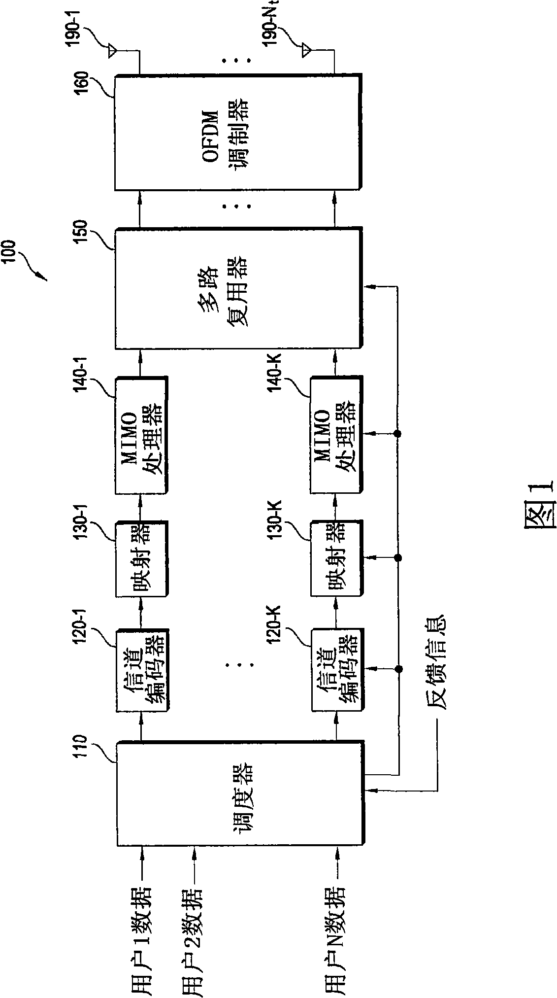
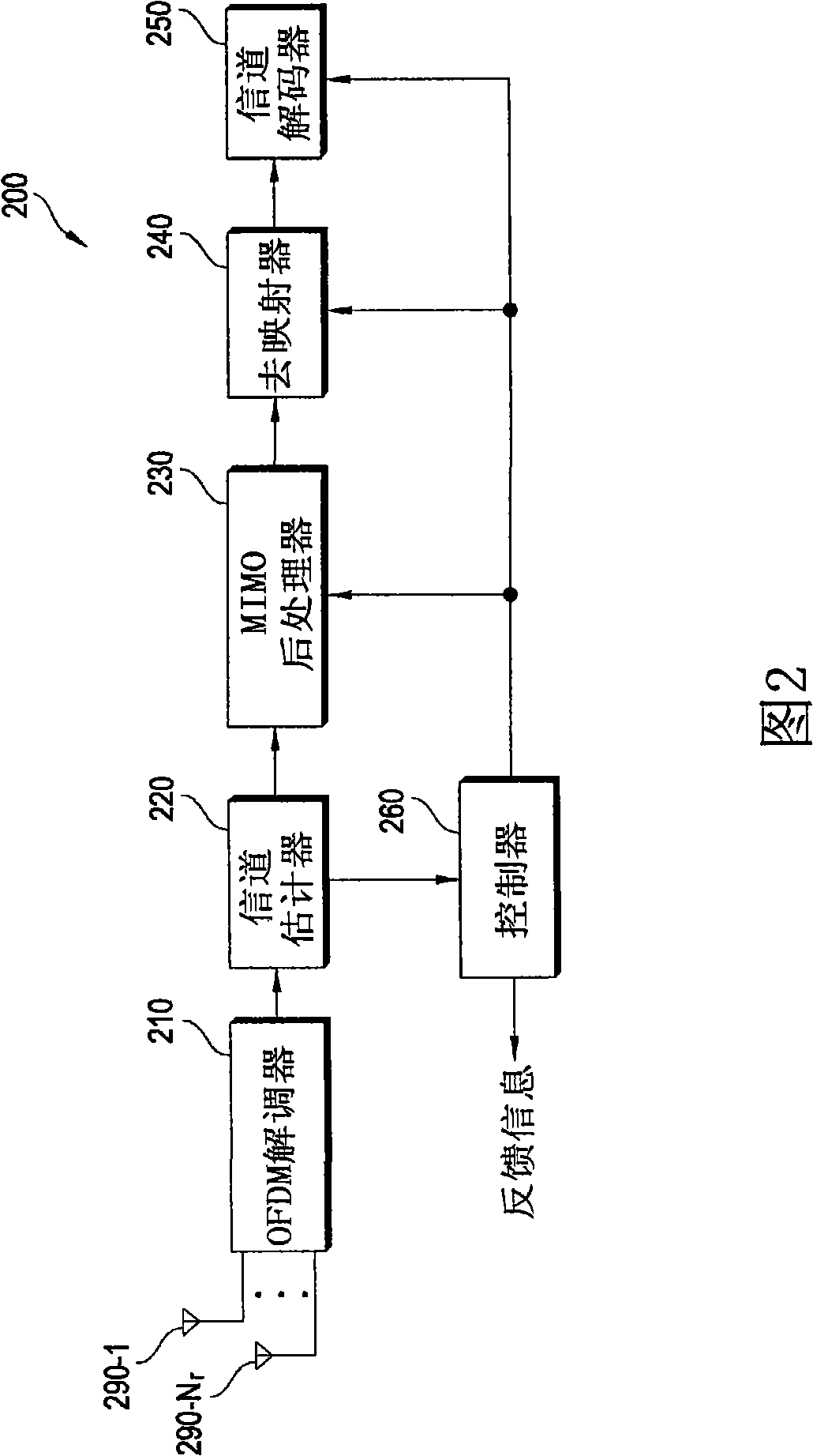
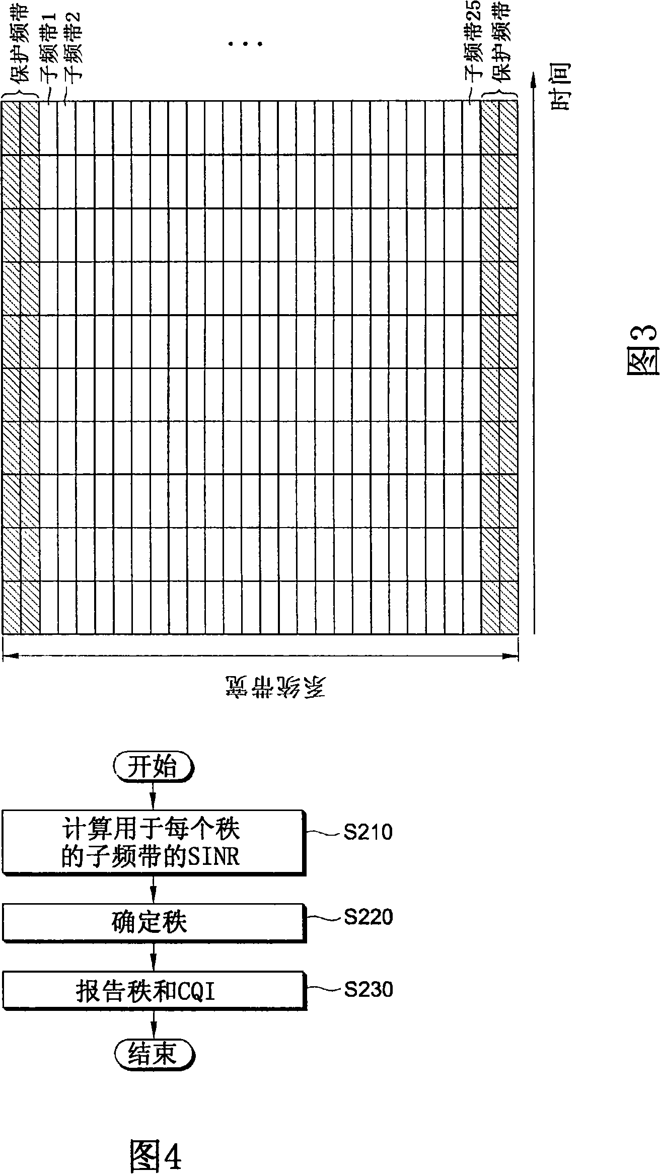
[0023] The techniques described below can be used in a variety of communication systems, including Code Division Multiple Access (CDMA) systems, Wideband CDMA (WCDMA) systems, Frequency Division Multiple Access (FDMA) systems, Orthogonal Frequency Division Multiplexing (OFDM) / Orthogonal Frequency Division Multiple Access (OFDMA) systems and the like. OFDM is a multi-carrier modulation technique used to efficiently divide the entire system bandwidth into multiple orthogonal sub-bands. Sub-bands may be called tones, sub-carriers, sub-channels, and so on.

[0024] The communication system may be a Multiple-Input Multiple-Output (MIMO) system, or a Multiple-Input Single-Output (MISO) system. MIMO systems use multiple transmit antennas and multiple receive antennas. MISO systems use multiple transmit antennas and a single receive antenna.

[0025] A base station (hereinafter referred to as BS) is a fixed station that communicates with user equipment, and a base station may be ...


PUM


Abstract

The present invention provides a method of reporting downlink channel information to a base station in a multiple antenna system. The method includes reporting a single rank for overall subband, the overall subband comprising a plurality of subbands and reporting a CQI for the single rank for at least one subband. Radio resources required for reporting channel information can be reduced and signaling overheads can be minimized.

Description

technical field [0001] The present invention relates to wireless communications, and more particularly, to a method of reporting downlink channel information in a multi-antenna system. Background technique [0002] Due to the generalization of information communication services, the advent of various multimedia services, the emergence of high-quality services, etc., the demand for communication services is rapidly increasing. Research on various wireless communication technologies is being conducted in various fields to meet such demands. [0003] A multiple-input multiple-output (MIMO) technology capable of transmitting multiple spatial streams simultaneously is required to achieve high spectral efficiency. MIMO technology employs multiple transmit antennas and one or more receive antennas. [0004] MIMO channels provided by multiple antennas can be decomposed into multiple independent channels. If the number of transmit antennas is Nt, and the number of receive antennas...

Claims


Application Information

Patent Timeline
Patent Type & Authority Applications(China)
IPC IPC(8): H04B7/26
Inventor 李旭峰任彬哲李文一高贤秀千珍英
Owner LG ELECTRONICS INC
Why Eureka
Try Eureka