Adjustable combined detacher

A disassembler and adjustable technology, which is applied in the field of tools, can solve the problems of difficulty in disassembly, disassembler can not be well adapted to disassembly operations, large differences in size, shape and position of circular ring parts, etc.

Inactive Publication Date: 2009-09-02
赵士华
View PDF0 Cites 7 Cited by
  • Summary
  • Abstract
  • Description
  • Claims
  • Application Information

AI Technical Summary

Problems solved by technology

[0002] In electromechanical equipment, there are ring-shaped parts such as bearings, gears, couplings, and motor wind fins. These ring-shaped parts are tightly sleeved on the shaft of the electromechanical equipment. , A large number of these ring-shaped parts are disassembled from the shaft. Since the cooperation between the ring-shaped parts such as bearings, gears, couplings, motor wind fins and the shaft is a transition fit, it is very difficult to disassemble. , sometimes it is disassembled with an ordinary disassembler, because there are many types of electromechanical equipment, and the shafts of different equipment and the ring-shaped parts on the shaft vary greatly in size, shape and position, and ordinary disassemblers cannot be well adapted to electromechanical equipment. The above-mentioned disassembly work during equipment maintenance
In the prior art, there is no combination that is convenient to use during the maintenance of electromechanical equipment and is suitable for disassembling bearings, gears, couplings, motor wind fins and other circular parts of different sizes, shapes and positions on the shafts of different electromechanical equipment. In the maintenance process of electromechanical equipment, when installing and disassembling bearings, gears, couplings, motor wind fins and other circular parts, because there is no suitable disassembler, maintenance personnel sometimes use hand hammers, sled rods, etc. Hard knocking and prying tools such as tools often cause damage to electromechanical equipment or components

Method used


Image

  • Adjustable combined detacher
  • Adjustable combined detacher
  • Adjustable combined detacher

Examples


Embodiment Construction

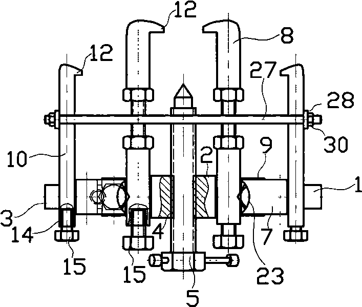
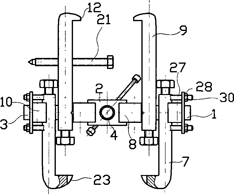
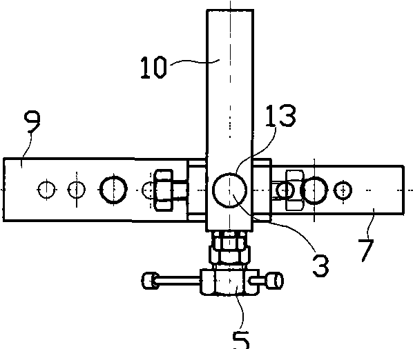
[0022] Figure 1 ~ Figure 1 0, the adjustable combined disassembler has a three-stage stepped round rod arm 1, the round rod arm has a middle segment 2 and two side arms 3, the outer diameter of the middle segment arm is larger, the length and outer diameter of the two side arms are equal, and the middle segment arm There is a radial through hole on it, which is the middle through hole 4. There is an internal thread in the middle through hole, and the main thread ejector rod 5 is rotated in the middle through hole. There is a radial through hole in the middle of a side arm, which is the side through hole 6. There are internal threads in the side through hole, and four pairs of pull hooks are symmetrically set on the arms on both sides. The four pairs of pull hooks are arc claw pull hook 7, variable rod pull hook 8, removal rod body pull hook 9 and short pull hook 10. The pull hook has a straight rod body 11 , the front end of the rod body has a hook claw 12 bent to one side, a...


PUM


Abstract

The invention provides an adjustable combined detacher, which has a three-section stepped round-bar arm, wherein the round-bar arm has a middle-section arm large in outer diameter and two side arms equal in length and outer diameter; the middle-section arm is provided with a radial through hole; an inner thread is arranged in the through hole; a main threaded ejector rod of which the outer wall has a thread matched with the inner thread in the through hole is screwed in the through hole; the two side arms are sleeved with four pairs of draw hooks, namely arc-claw draw hooks, shift-lever draw hooks, detaching-rod draw hooks and short draw hooks; each draw hook is provided with a straight rod body; the front end of each rod body is provided with a hook claw bending to one side; the rod body behind the rod body is provided with round holes matched with the two side arms; the axis of the round holes is perpendicular to the length direction of the rod bodies; the axis direction of the round holes is identical with the bending direction of the hook claws; the back end of each rod body is provided with a top screw; and a quadrilateral hoop frame formed by endplate bolts is arranged between one pair of opposite draw hooks. As the detacher has four pairs of different draw hooks, the detacher is suitable to detach bearings, gears, couplings, motor blades and other annular parts in different size, shapes and positions on different electromechanical-equipment shafts when electromechanical equipment is overhauled.

Description

technical field [0001] The invention relates to a tool used by a mechanic fitter when overhauling electromechanical equipment, in particular to a tool used by a mechanic fitter to disassemble bearings, gears, couplings, motor wind fins and other circular components from shafts when overhauling electromechanical equipment Tool of. Background technique [0002] In electromechanical equipment, there are ring-shaped parts such as bearings, gears, couplings, and motor wind fins. These ring-shaped parts are tightly sleeved on the shaft of the electromechanical equipment. , A large number of these ring-shaped parts are disassembled from the shaft. Since the cooperation between the ring-shaped parts such as bearings, gears, couplings, motor wind fins and the shaft is a transition fit, it is very difficult to disassemble. , sometimes it is disassembled with an ordinary disassembler, because there are many types of electromechanical equipment, and the shafts of different equipment an...

Claims


Application Information

Patent Timeline
Patent Type & Authority Applications(China)
IPC IPC(8): B25B27/14
Inventor 赵士华
Owner 赵士华
Why Eureka
Try Eureka