Two-way directional force output air-powered flexible drive device

A driving device and flexible driver technology, applied in the direction of manipulators, manufacturing tools, etc., can solve the problems of poor radial rigidity, small stroke, single force, etc., and achieve the effect of large power/mass ratio and large working stroke

Inactive Publication Date: 2009-09-09
ZHEJIANG UNIV OF TECH
View PDF1 Cites 13 Cited by
  • Summary
  • Abstract
  • Description
  • Claims
  • Application Information

AI Technical Summary

Problems solved by technology

[0003] In order to overcome the disadvantages of poor radial rigidity, too single acting force and too small stroke of the pneumatic flexible driver in the prior art, the present invention provides a flexible, flexible, high rigidity, large stroke, and close to biological muscle movement form. Pneumatic flexible drive device with two-way force output

Method used


Image

  • Two-way directional force output air-powered flexible drive device
  • Two-way directional force output air-powered flexible drive device
  • Two-way directional force output air-powered flexible drive device

Examples


Embodiment Construction

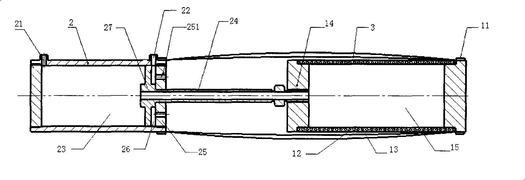
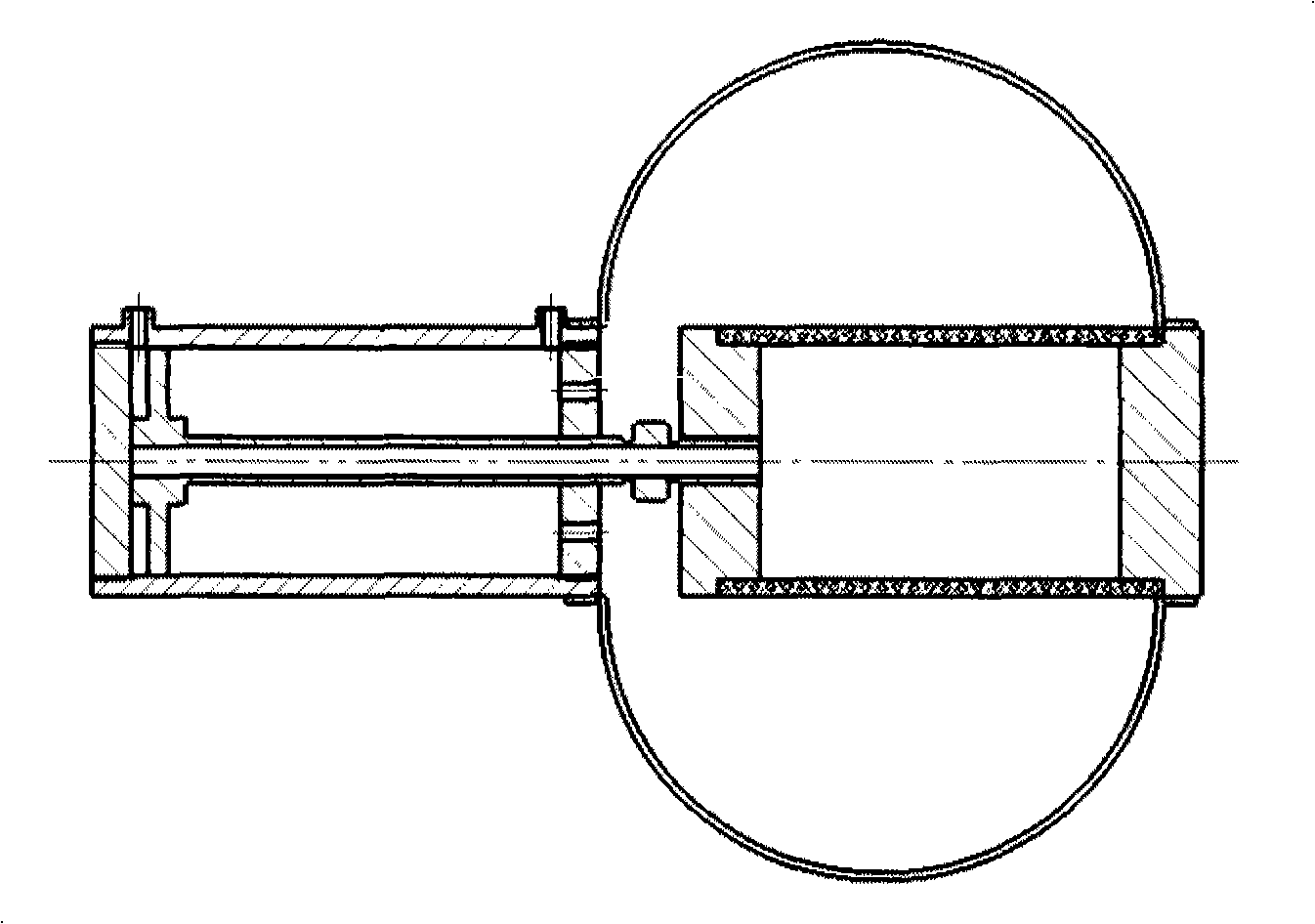
[0013] combine figure 2 , 3 , to further illustrate the present invention:

[0014] The pneumatic flexible driving device with two-way force output includes a pneumatic flexible driver composed of end caps 11, 14, a first rubber tube 12, and a spring 13 nested in the wall of the first rubber tube 12. The pneumatic flexible driver There is a piston cylinder 2 in the front, and a second rubber tube 3 is airtightly sleeved outside the pneumatic flexible driver, and the front end of the second rubber tube 3 is airtightly sleeved on the rear end cover 25 of the piston cylinder 2 On; described piston cylinder 2 has front air port 21 and rear air port 22, and piston 27 is positioned between described front air port 21 and rear air port 22; Described piston 27 connects a hollow piston rod 24, and described piston The rear end of the rod 24 is connected to the front end cover 14 of the pneumatic flexible driver, and the piston rod 24 communicates with the front inner cavity 23 of th...


PUM


Abstract

The invention discloses a two-way directional force output air-powered flexible drive device, comprising an end cover, a first rubber tube, and an air-powered flexible drive device constructed by springs embedded in the wall of the rubber tube; a piston cylinder is arranged in front of the air-powered flexible drive device, a second rubber tube is sheathed outside the air-powered flexible drive device in an air-tight way, and the front end of the second rubber tube is sheathed at the rear end cover of the piston cylinder; the piston cylinder is provided with a front airport and a rear airport with a piston body arranged between the front airport and the rear airport; the piston body is connected with a hollow piston rod, the rear end of the piston rod is connected with the front end cover of the air-powered flexible drive device, and the piston rod is communicated with the inner cavity of the piston cylinder communicating the front airport and the inner cavity of the air-powered flexible drive device; the rear end cover of the piston rod is provided with through holes which is communicated with the inner cavity of the piston cylinder communicating the rear airport and the inner cavity of the second rubber tube. The invention has the advantages of flexible motion, good flexibility, high stiffness, large stroke and similar movement mode with the animal muscles.

Description

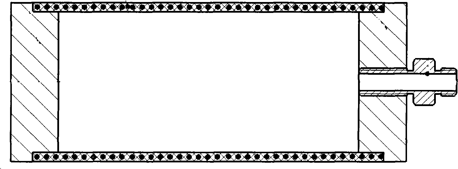
technical field [0001] The invention belongs to the pneumatic flexible driver and has good application prospects in agricultural robots, medical robots, service robots and other occasions. Background technique [0002] Pneumatic flexible actuators have the advantages of simple structure, clean and pollution-free, large power-to-weight ratio, and flexibility, and overcome the disadvantages of large structural size and difficulty in miniaturization of motor drives. Applications. However, the pneumatic flexible actuator also has some shortcomings such as the contradiction between flexibility and rigidity, and hysteresis. A kind of pneumatic flexible driver is proposed, such as patent No. CN2790700: the patent name is a kind of pneumatic flexible driver (such as figure 1 ), which discloses a pneumatic flexible driver comprising a left end cover, a rubber tube, a spring nested in the wall of the rubber tube, a right end cover, and a pipe joint, and the two ends of the rubber tu...

Claims


Application Information

Patent Timeline
Patent Type & Authority Applications(China)
IPC IPC(8): B25J13/00
Inventor 鲍官军张庆丰杨庆华高峰
Owner ZHEJIANG UNIV OF TECH
Why Eureka
Try Eureka