Coding of an information signal

A signal and encoder technology, applied in the field of SBR encoding, which can solve the problems of high number of bits and unsuitable for short delay time.

Active Publication Date: 2009-09-09
FRAUNHOFER GESELLSCHAFT ZUR FOERDERUNG DER ANGEWANDTEN FORSCHUNG EV
View PDF0 Cites 33 Cited by
  • Summary
  • Abstract
  • Description
  • Claims
  • Application Information

AI Technical Summary

Problems solved by technology

Although this prevents pre-echo, this scheme is not suitable for applications requiring short delay ti...

Method used


Image

  • Coding of an information signal
  • Coding of an information signal
  • Coding of an information signal

Examples


Embodiment Construction

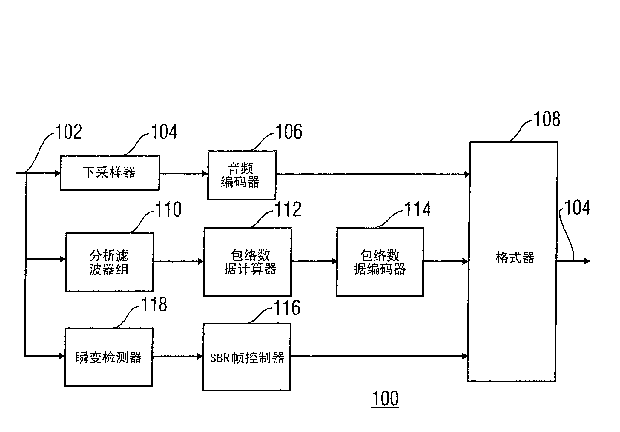
[0037] figure 1 The architecture of an encoder according to one embodiment of the invention is shown. As an example, figure 1 The encoder of is an audio encoder generally indicated by reference numeral 100 . The encoder comprises an input 102 of the audio signal to be encoded and an output 104 of the encoded audio signal. It is assumed below that the audio signal in the input 102 is a sampled audio signal, such as a PCM encoded signal. However, figure 1 The encoder of can also be implemented in different ways.

[0038] figure 1 The encoder also includes a downsampler 104 and an audio encoder 106 connected in the order mentioned between the input 102 and the first input of the formatter 108, the output of the formatter 108 This in turn is connected to the output 104 of the encoder 100 . Due to the connection of parts 104 and 106 , the encoding of the downsampled audio signal 102 ends at the output of an audio encoder 106 , which in turn corresponds to the encoding of...


PUM


Abstract

The problem of transients can be addressed satisfactorily and a further decoding delay can be reduced for this if use is made of a new SBR frame class in which the frame limits (902a, 902b) are not shifted, that is to say the grid limits are still synchronized with the frame limits (902a, 902b), but in which a statement of the transient position is also used as a syntax element in order to be used, within the frames of this new frame class, to determine the grid limits within these frames at the coder and/or decoder end.

Description

technical field [0001] The invention relates to information signal coding, such as audio coding, and in this context in particular SBR (Speed ​​Band Replication) coding. Background technique [0002] In the context of encoding audio signals in applications with very small available bit rates, it is known to use SBR techniques for encoding. Only the low frequency part is fully coded, ie with sufficient temporal and spatial resolution. For the high frequency part, only the spectral envelope or the envelope of the spectral time curve of the audio signal is detected and encoded. On the decoder side, the low frequency components are obtained from the encoded signal and are then used to reconstruct or "copy" the high frequency components from the signal. However, in order to adapt the energy of the pre-reconstructed high-frequency part to the actual energy in the high-frequency part of the original audio signal, the pre-reconstructed high-frequency part is processed at the decod...

Claims


Application Information

Patent Timeline
IPC IPC(8): G10L19/02G10L21/02G10L19/025G10L21/038H04L47/43
CPCG10L19/025G10L21/038G10L19/02G10L21/02H03M7/30
Inventor 马库斯·施内尔迈克尔·舒尔特曼弗雷德·卢茨基曼努埃尔·扬德尔
Owner FRAUNHOFER GESELLSCHAFT ZUR FOERDERUNG DER ANGEWANDTEN FORSCHUNG EV
Why Eureka
Try Eureka