Production method of shoe heel steel pipe

A manufacturing method and technology for steel pipes, applied in the field of manufacturing heel steel pipes, can solve the problems of waste of strips, high cost of molds, difficult to estimate mold costs, etc., and achieve the effects of increasing production capacity, reducing costs, and reducing the number of specifications.

Inactive Publication Date: 2009-09-16
晏扬工业股份有限公司
View PDF0 Cites 4 Cited by
  • Summary
  • Abstract
  • Description
  • Claims
  • Application Information

AI Technical Summary

Problems solved by technology

[0004] However, the above-mentioned continuous stamping method can certainly improve the operation efficiency and reduce the cost of the finished product, but the cost of the mold is relatively high, and if it is desired to produce steel pipes with the same outer diameter but different lengths, another set of molds must be replaced. If there are steel pipes of various specifications with different outer diameters and different lengths, the cost of the mold is even more difficult to estimate
[0005] In addition, when the finished steel pipe is punched from the above-mentioned strip, the strip must be reserved for clamping and positioning during transportation and stamping, so when the steel pipe is completed, there will be surplus material, which can only be used as waste. It cannot be recycled, so unnecessary waste of the strip is caused, and its cost will be passed on to the finished product.

Method used


Image

  • Production method of shoe heel steel pipe
  • Production method of shoe heel steel pipe
  • Production method of shoe heel steel pipe

Examples


Embodiment Construction

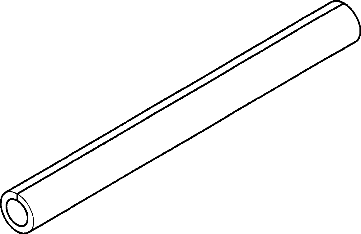
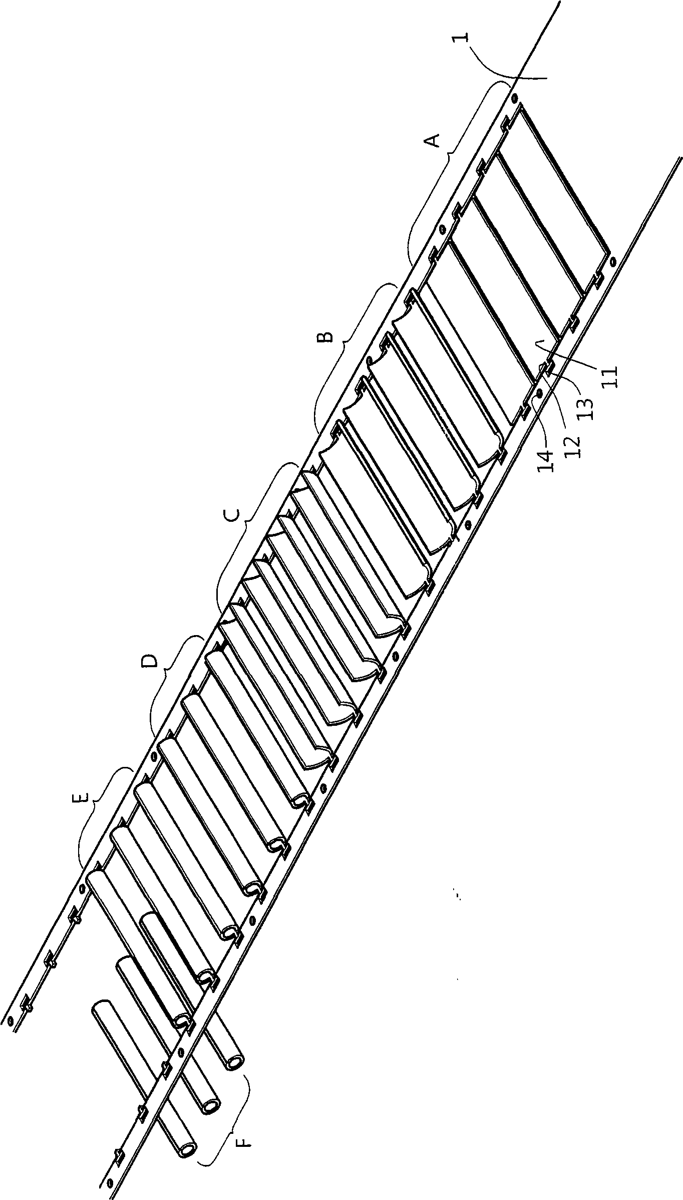
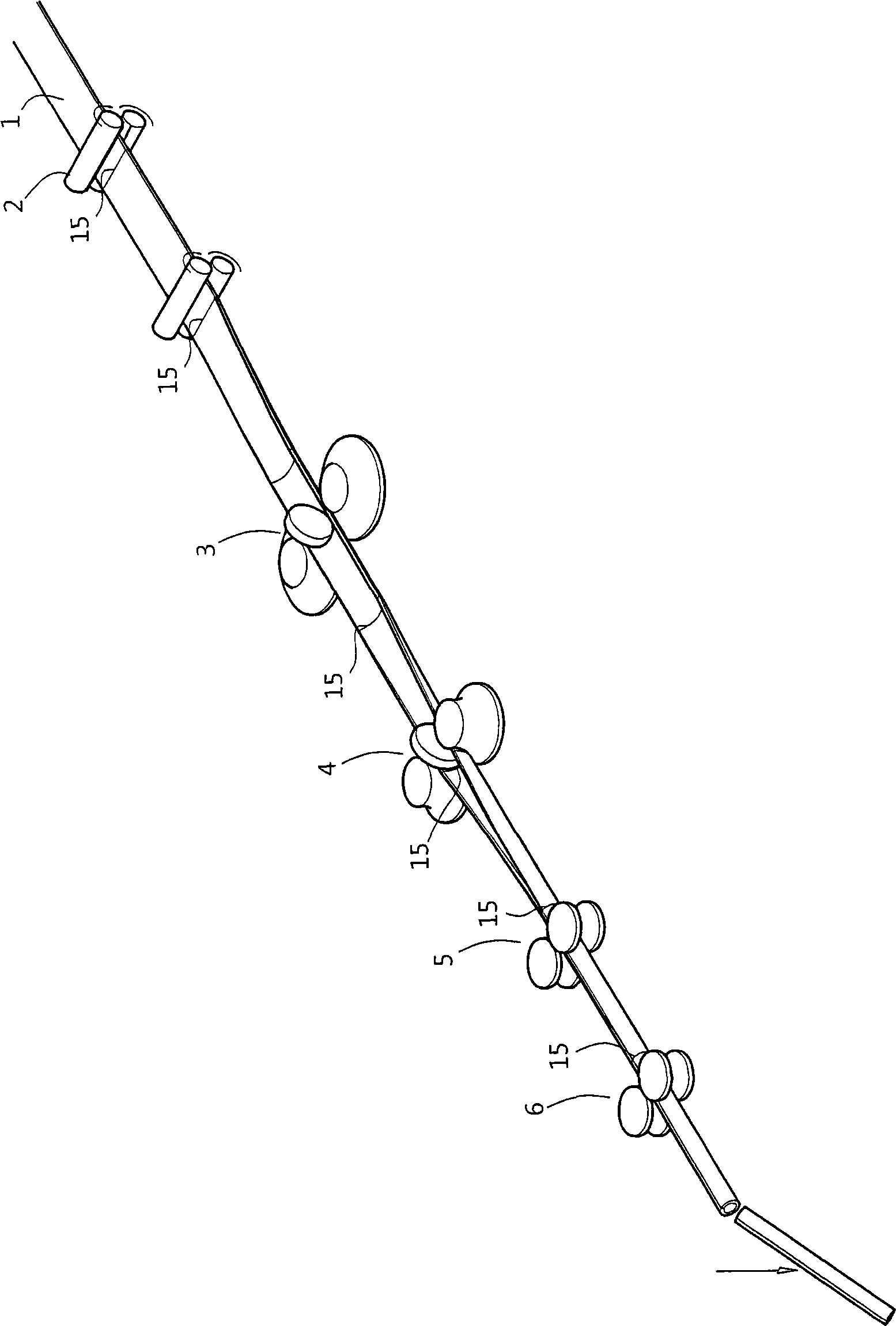
[0018] Please refer to image 3 As shown, the present invention is a method for continuous rolling and rolling of steel pipes. The steps are to send the strip 1 to the shearing and pressing wheel 2 via the conveying wheel, and perform the shearing and pressing process of the fracture mark 15, and each formed fracture The distance between the marks 15 is the length of the steel pipe to be made, and then the strip 1 is continuously conveyed to pass through the first rolling wheel set 3 (such as Figure 4 As shown), the strip 1 is bent into a predetermined arc-shaped prototype, and then passed through the second rolling wheel set 4 (such as Figure 5 As shown), the strip 1 of the arc-shaped prototype is bent into a semi-elliptical shape again, and then continues to pass through the third rolling wheel set 5 (such as Image 6 As shown), the semi-elliptical strip 1 is rolled into a nearly circular pipe, and then continues to pass through the fourth rolling wheel set 6 (such as F...


PUM


Abstract

The invention provides a production method of a shoe heel steel pipe, more particularly relates to the fixed pipe which is embedded in the shoe heel and used for being knocked in by a pinned top-piece, and the invention uses a continuous rolling method for forming to replace the punch forming of a progressive die. The method is characterized in that a band material is firstly subjected to compression-sheering forming at breaking mark in accordance with predetermined length of the steel pipe, and then the band material is rolled continuously by a plurality of groups of rolling wheels with different curvatures so that the flat-shaped band material are rolled into the expected shape of a round pipe, and finally the shaped pipe material is broken off at the previous breaking mark. Therefore the heel steel pipe with required length and outside diameter is formed. Through the above method of continuous rolling, uninterrupted continuous production of steel pipes can be carried out, which enhances the production efficiency. All the steel pipes with the same diameter but different lengths can be manufactured by the same group of rolling wheel, thus being capable of reducing expenses and costs of the mold substantially.

Description

technical field [0001] The invention relates to a steel pipe planted in the heel of a shoe. Firstly, the strip is continuously formed with fracture marks, then the strip is rolled into a tubular shape by continuous rolling, and finally the finished product of the steel pipe is obtained by performing the breaking operation. Background technique [0002] Generally, the steel pipe planted in the heel of high-heeled shoes is used to enhance the strength of the heel, and is a component that is combined with the shoe body and the pad body for nailing into the sky. The structure of the steel pipe as we know it is as follows: figure 1 As shown, it is rolled from a flat leather-like material. If it is rolled by stamping, it may require at least six stamping steps, which may include punching, bending, stretching, and cutting. If you separate the steps one by one For processing, six sets of equipment and six labors are required, and each operator needs to perform feeding and unloading ...

Claims


Application Information

Patent Timeline
Patent Type & Authority Applications(China)
IPC IPC(8): B21D5/12
Inventor 程进浩
Owner 晏扬工业股份有限公司
Why Eureka
Try Eureka