A device and method for cutting and collecting the tail shank of the steel wire screw sleeve of the complex blind cavity receiver

A technology of wire thread sleeves and tail handles, which is applied in the field of devices for cutting and collecting wire thread sleeve tail handles in aluminum-magnesium alloy casings and other types of casings, and can solve problems such as polluted parts, wire thread sleeve scrapping, and low work efficiency. Achieve convenient use and management, reduce the number of parts, and save costs

Active Publication Date: 2017-05-17
AECC AVIATION POWER CO LTD
View PDF5 Cites 0 Cited by
  • Summary
  • Abstract
  • Description
  • Claims
  • Application Information

AI Technical Summary

Problems solved by technology

[0005] 1. The blind cavity of the box body is mostly an air channel. When the tail handle falls into the cavity, it is not easy to find it, and it is very difficult to take it out with the existing method, which brings great difficulties to the work of assembling the wire screw sleeve. If the tail handle is left in the cavity, it will cause a catastrophic disaster to the engine;
[0006] 2. If you use needle-nose pliers to remove the tail handle, one is that the space is limited and the clamping is unstable; the other is that it is difficult to control the lateral swing, and it is easy to pull the last turn of the wire screw sleeve and cause the wire screw sleeve to be scrapped;
[0007] 3. When installing a small-sized wire thread sleeve, due to the small hole and small space, it is impossible to use tweezers to pick it up. It is generally used to dip the tail handle with a steel wire coated with butter after punching off the tail handle; this method exists Disadvantages: too little butter, unable to take out the tail shank, too much butter, the threaded hole is blocked by pollution, it is difficult to observe the position of the tail shank and the tail shank is stuck in the hole when taking it out and it is difficult to take it out. It is not easy to grasp the amount of butter used in this method. The method is time-consuming and laborious, the work efficiency is extremely low, and the parts are polluted

Method used


Image

  • A device and method for cutting and collecting the tail shank of the steel wire screw sleeve of the complex blind cavity receiver
  • A device and method for cutting and collecting the tail shank of the steel wire screw sleeve of the complex blind cavity receiver
  • A device and method for cutting and collecting the tail shank of the steel wire screw sleeve of the complex blind cavity receiver

Examples


Embodiment Construction

[0040] The present invention will be further described below in conjunction with the accompanying drawings.

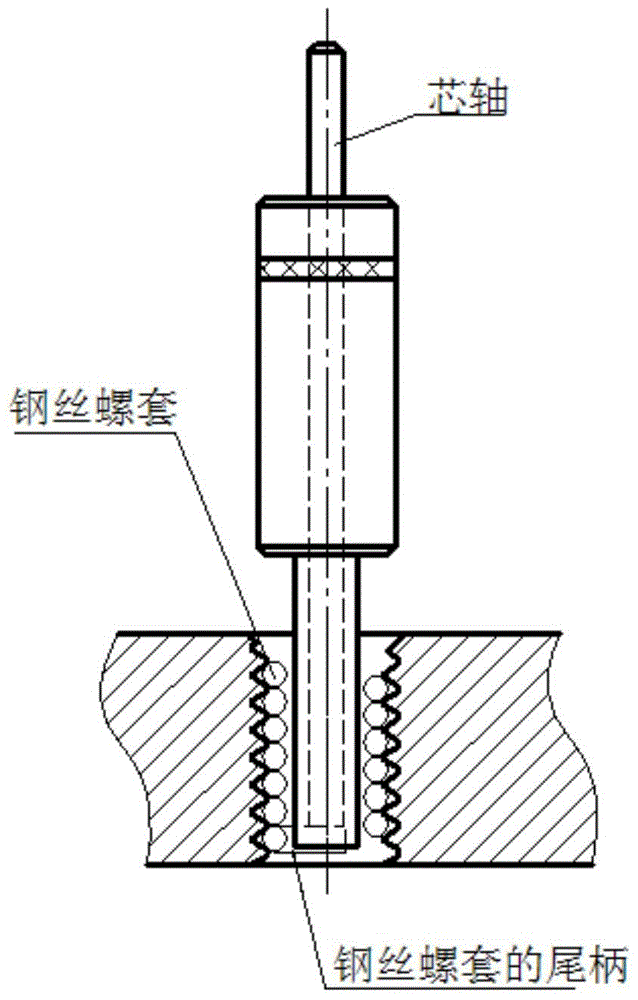
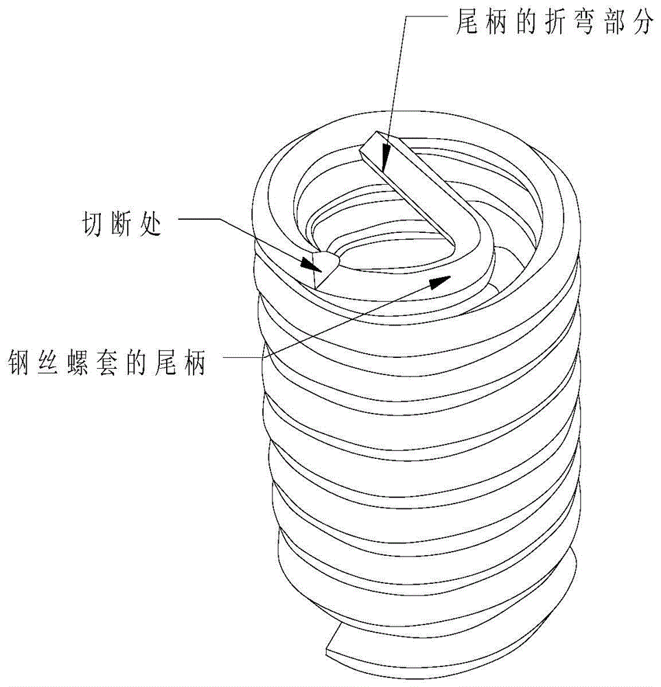
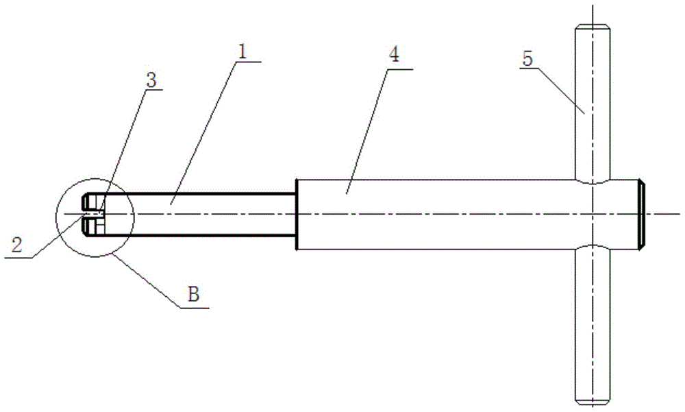
[0041] Such as image 3 , Figure 4 , Figure 5 and Figure 6 As shown, a device for cutting off and collecting the tail handle of the wire screw sleeve of the complex blind cavity casing includes a connecting rod 4, a handle rod 5 and a guide mandrel 1 that can be inserted into the inner hole of the wire screw sleeve. The guide mandrel The cross-sectional shape of 1 is circular, and the diameter of the guide mandrel 1 is smaller than the minimum inner diameter of the inner hole of the wire screw sleeve; the end of one end of the guide mandrel 1 is provided with a groove A 2 inwardly along the length direction of the guide mandrel 1, and the After the guide mandrel 1 is inserted into the inner hole of the wire screw sleeve, the bent part of the tail handle of the wire screw sleeve can enter the groove A2 along the opening of the groove A2, and the width of the groov...


PUM


Abstract

The invention belongs to the technical field of new manufacturing and maintaining of a casing part with a steel wire thread sleeve needing to be mounted in a space flight and aviation gas turbine engine, and particularly relates to a device and method for cutting off and collecting the steel wire thread sleeve mounted on a casing with a complex blind cavity. The device comprises a connecting rod, a hand shank rod and a guide core bar. A groove A is formed in the portion of one end of the lead core bar. After a tail shank is inserted along an inner hole of the steel wire thread sleeve, the bent part of the tail shank can enter along an opening of the groove A, a groove B is formed in the circumferential direction of the groove A, a certain included angle is formed by the groove B and the groove A, and after the bent part of the tail shank enters the groove A, the lead core bar is rotated so that the bent part can enter the groove B. The other end of the lead core bar is connected with one end of the connecting rod, and the other end of the connecting rod is connected with the hand shank rod used for enabling the guide core bar and the connecting rod to rotate. Two process steps of cutting off the tail shank and taking out the waste tail shank of a previous steel wire thread sleeve assembling technology are combined into one process step of cutting off and taking out, the tail shank is taken out while being cut off, and broken tail shanks do not need to be found any more.

Description

[0001] 【Technical field】 [0002] The invention belongs to the technical field of new manufacture and maintenance of box body parts that need to be installed with wire screw sleeves in gas turbine engines of aerospace and aviation, and specifically relates to an aluminum-magnesium alloy casing used for complex blind cavities and other types of casings for cutting and collecting wire screws. Device and method for putting on tail handle. [0003] 【Background technique】 [0004] At present, the traditional general-purpose method of installing the wire thread sleeve of the casing is generally adopted. The method is: first use the inserter to insert the wire thread sleeve into the mounting hole of the casing, and then hit the flat tail cutter with a hand hammer. The mandrel of the flat tail cutter cuts off the tail handle of the wire thread sleeve, such as figure 1 shown, and then remove the peduncle with suitable small tweezers. If the installation hole of the wire threaded sleev...

Claims


Application Information

Patent Timeline
Patent Type & Authority Patents(China)
IPC IPC(8): B21F11/00
CPCB21F11/005
Inventor 孟繁翎周清理焦倩齐玮凤宋磊孟繁弘吴嘉涛秦俊峰
Owner AECC AVIATION POWER CO LTD
Why Eureka
Try Eureka