Microwave oven-compatible paper cup

A technology for microwave ovens and paper cups, which can be used in papermaking, packaging paper, paper/cardboard containers, etc., and can solve the problems of high material costs and manufacturing costs

Inactive Publication Date: 2009-09-16
DAI NIPPON PRINTING CO LTD
View PDF0 Cites 29 Cited by
  • Summary
  • Abstract
  • Description
  • Claims
  • Application Information

AI Technical Summary

Problems solved by technology

However, they have the problem of high material cost and manufacturing cost

Method used


Image

  • Microwave oven-compatible paper cup
  • Microwave oven-compatible paper cup
  • Microwave oven-compatible paper cup

Examples


no. 1 example

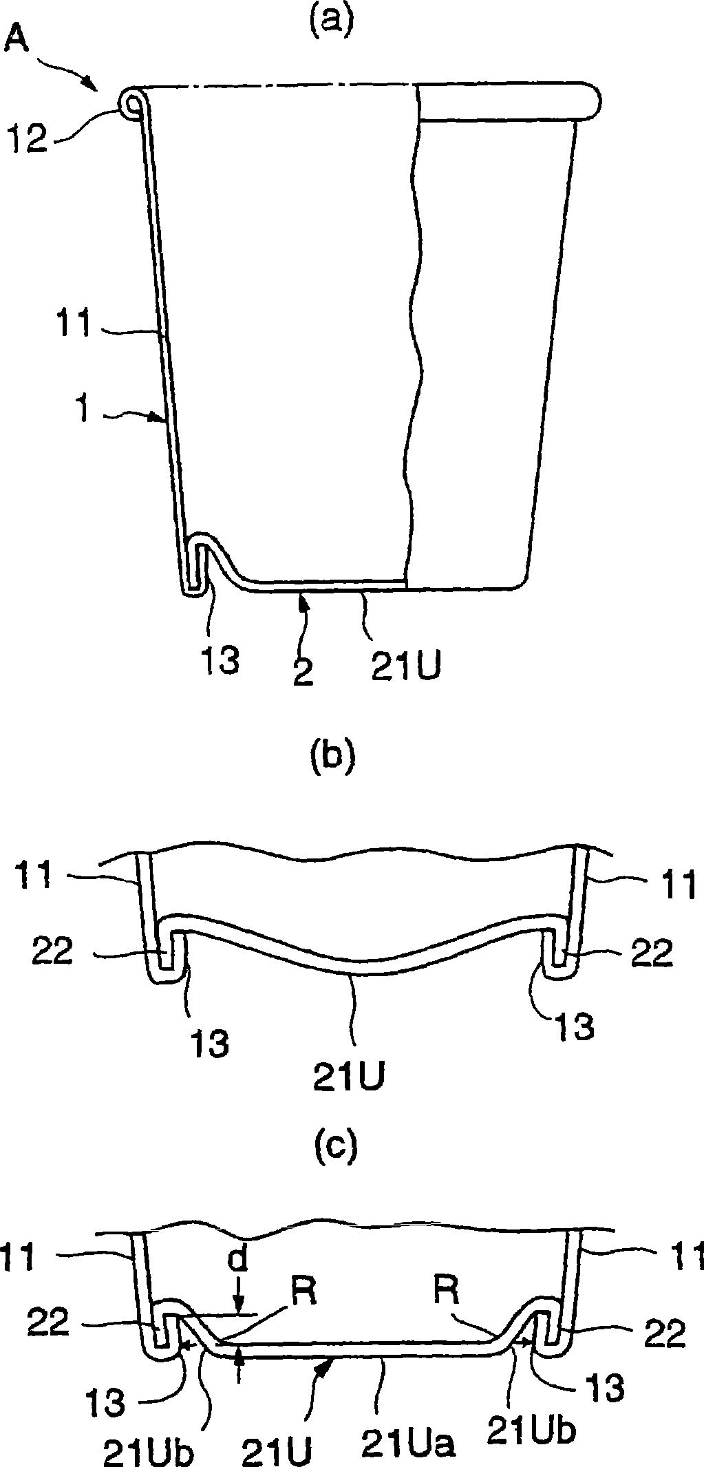
[0098] figure 1 Shown is a partial sectional view of a paper cup for a microwave oven according to a first embodiment of the present invention. Such as figure 1 As shown in (a), the paper cup for microwave oven is provided with a cup body member 1 and a bottom member 2 . The cup body member 1 is composed of a cup body portion 11 , a top curled portion 12 formed by curling the upper end of the cup body portion 11 outward, and an upturned portion 13 formed by turning the lower end of the cup body portion 11 inwardly. Here, the bottom member 2 is composed of a bottom portion 21U which is modified to be concave downward when viewed from the inner surface side, and a curved portion 22 perpendicular to the outer peripheral portion of the bottom portion 21U at a right angle. formed by bending downwards. The bent portion 22 of the bottom member 2 is sandwiched between the upturned portion 13 of the cup body member 1 and the lower end portion of the cup body portion 11, and joins ...

no. 2 example

[0131] Next, the following description will discuss a paper cup for a microwave oven according to a second embodiment of the present invention. In such paper cups, the body member and the bottom member are foamed to provide thermal insulation. The construction of the paper cup before the parts are foamed is the same as that of the paper cup A in the first embodiment described above. However, the material construction of the cup body member and the bottom member are different.

[0132] In other words, if Figure 19 As shown in (a), the material configuration before the foamed state of the cup body member 1 or bottom member 2 of this embodiment basically includes a surface thermoplastic resin layer 5, a paper layer 3 as a basic layer, and a back thermoplastic resin layer. Layer 6, the above three are arranged in the above order from the surface side. After being foamed, such as Figure 19 As shown in (b), the material configuration includes a foamed layer 5a, a paper layer 3...

no. 3 example

[0146] Next, the following description will discuss a paper cup for a microwave oven according to a third embodiment of the present invention. Such as Figure 23 As shown in (a), the microwave oven paper cup E of this embodiment is provided with a cup body member 1 , a bottom member 2 and a heat insulating member 7 . The configurations of the body member 1 and the bottom member 2 are the same as those of the paper cup A of the first embodiment. A heat insulating member 7 made of a material having heat insulating properties is pasted to the outer surface of the bottom surface portion 21U of the bottom member 2 .

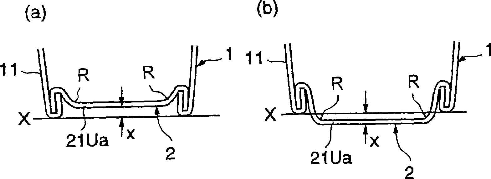
[0147] Such as Figure 23 As shown in (b), in this embodiment, the bottom surface portion 21U is formed in a concave shape extending downward when viewed from the inner surface side, that is, a U-shape. Such as Figure 23 As shown in (c), the bottom surface part 21U is preferably shaped as a dish formed by the lower surface part 21Ua and the wall part 21Ub, the lo...


PUM

PropertyMeasurementUnit
thicknessaaaaaaaaaa
thicknessaaaaaaaaaa

Abstract

This invention provides a microwave oven-compatible paper cup capable of preventing a thread end part from being burnt when the paper cup containing a content such as beverage and instant food is heated for cooking by a microwave oven, comprising a shell member (1) having a cylindrical shell part (11), a top curl part (12) formed by bending the upper end side of the shell part, and a folded part (13) formed by folding up the lower end of the shell part inward, and a bottom member (2) having a bottom surface part (20) and a bent part (22) formed by bending the outer peripheral edge part of the bottom surface part, wherein the bent part (22) is sandwiched between the shell part (11) and the folded part (13) to connect the shell member (1) to the bottom member (2), and the bottom surface part (20) is formed recessedly downward and including a lower surface section, which is almost flat.

Description

technical field [0001] The invention relates to a paper cup for a microwave oven. Background technique [0002] In general, paper cups have been widely used as containers for hot drinks, instant foods sold in vending machines, and the like. In some cases, paper cups containing beverages or food are placed directly into the microwave, where they are heated and cooked. Such as Figure 51 As shown, a commonly used paper cup P is provided with a cup body member 1 and a bottom member 2 . The cup body member 1 mainly forms a cup body portion 11 . The top end of the cup body member 1 is curled outward to form a top curled portion 12 , and the bottom end of the cup body member 1 is bent inward to form an upturned portion 13 . Here, the bottom member 2 mainly forms the bottom surface portion 21 . A peripheral portion of the bottom member 2 is bent vertically downward at a right angle to form a bent portion 22 . By sandwiching the bent portion 22 of the bottom member 2 between th...

Claims


Application Information

Patent Timeline
Patent Type & Authority Applications(China)
IPC IPC(8): B65D3/10B65D3/22B65D3/28B65D65/40B65D81/34A47G19/22B32B1/02B32B27/10B31C1/06B31B50/00
Inventor 野崎达也远藤宪一森迫健小坂智洋
Owner DAI NIPPON PRINTING CO LTD
Why Eureka
Try Eureka