Method of using light-emitting diode (LED) lighting to illuminate the interior of microwave ovens

a technology of light-emitting diodes and microwave ovens, which is applied in the direction of lighting and heating apparatus, domestic cooling apparatus, furnaces, etc., can solve the problems of high filament temperature, bulb burning out, and bulb being vulnerable to microwaves, and achieve good contrast ratio

Inactive Publication Date: 2012-07-05
GENERAL ELECTRIC CO
View PDF2 Cites 62 Cited by
  • Summary
  • Abstract
  • Description
  • Claims
  • Application Information

AI Technical Summary

Benefits of technology

[0007]The present disclosure provides a high-intensity light-emitting diode (LED) light within the cooking cavity of a microwave oven, so that the cont

Problems solved by technology

Unfortunately, such bulbs are vulnerable to microwaves, because the filament can receive microwave energy which will heat the filament to destructive levels.
High oven temperatures, when added to the heating effects of the microwaves in addition to the heating effects of the AC current supply, can quickly raise the filament temperature above its rated value, thus quickly burning out the bulb.
A problem with this solution is such a placement of the bulb results in a significant reduction in the amount of available light for the cav

Method used


Image

  • Method of using light-emitting diode (LED) lighting to illuminate the interior of microwave ovens
  • Method of using light-emitting diode (LED) lighting to illuminate the interior of microwave ovens
  • Method of using light-emitting diode (LED) lighting to illuminate the interior of microwave ovens

Examples


Embodiment Construction

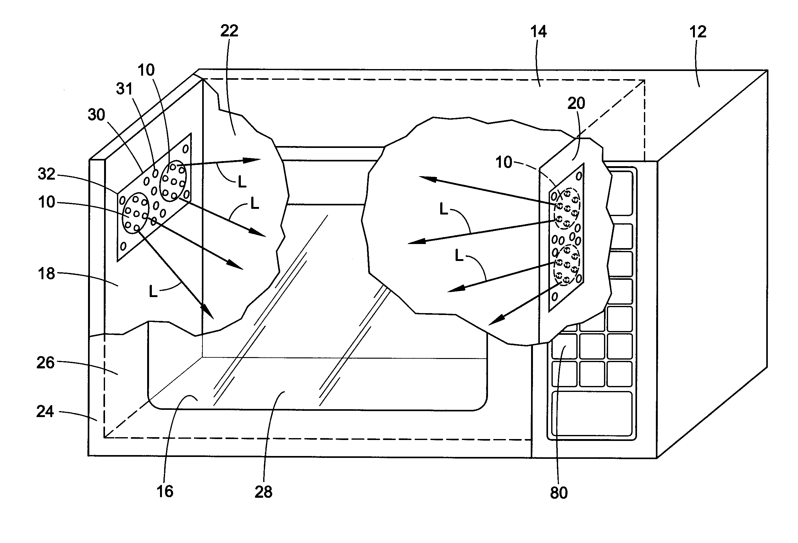
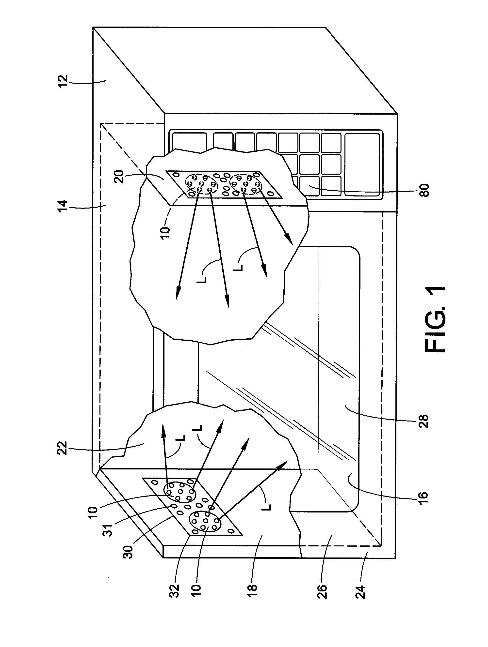
[0022]A conventional microwave oven has a front door, a rear wall, interior side walls and a floor or bottom wall forming an interior chamber or cavity of the oven. In existing microwaves, a standard appliance-type tungsten filament lamp is positioned in a chamber or panel within one or more of the side walls. The lamp is positioned to be out of the path of microwaves within the cavity. In addition, a screen covers the lamp within the chamber or panel.

[0023]In addition to a reduced amount of light being available from the incandescent lamp because of its location in the chamber, the screen reduces the available light by another 50 percent or so, so that a 25 watt bulb effectively delivers only about 4% of its emitted light to the oven cavity in a conventional microwave oven. In addition, the location of the chamber is generally on a side wall of the oven so that the contents of the oven are lit only from the sides, so much of the incident light is not directed toward the oven door, ...


PUM


Abstract

A Light Emitting Diode light system for a domestic appliance includes a Light Emitting Diode light panel mounted on a first wall of the appliance. Light Emitting Diodes are mounted along a periphery of the panel for emitting light through a first surface of the panel. A second reflective surface is formed opposite the first surface of the panel. A diffuser is provided for diffusing light emitted by the Light Emitting Diodes. A power supply source connected to the Light Emitting Diode panel for providing power to the panel. A method of illuminating the interior of a microwave oven includes providing a first Light Emitting Diode panel mounted on a first wall of the microwave; providing a second Light Emitting Diode panel mounted on the first wall of the microwave; providing a diffuser for diffusing light emitted by the light emitting diodes; and providing a power supply source connected to the Light Emitting Diode panel to provide power to the panel.

Description

BACKGROUND OF THE DISCLOSURE[0001]The present disclosure relates to a method and apparatus for improved lighting of the interior of microwave ovens. More particularly, it relates to the use of light-emitting diodes (LEDs) to illuminate the interior of microwave ovens.[0002]The interior of existing microwave ovens are typically illuminated by a small, tungsten filament appliance lightbulb, typically of 25 watts, radiating 200 lumens, and having a life expectancy of about 200 hours. Unfortunately, such bulbs are vulnerable to microwaves, because the filament can receive microwave energy which will heat the filament to destructive levels. High oven temperatures, when added to the heating effects of the microwaves in addition to the heating effects of the AC current supply, can quickly raise the filament temperature above its rated value, thus quickly burning out the bulb.[0003]One existing way of minimizing damage to the light bulb is to locate the lightbulb in one of the interior side...

Claims


Application Information

Patent Timeline
IPC IPC(8): F25D27/00
CPCH05B6/6444
Inventor DO, TERRY LIEN
Owner GENERAL ELECTRIC CO
Why Eureka
Try Eureka