Beam-column type support and method for constructing multi-section adjacent bridges using same

A beam-column and bridge technology, which is applied to the preparation and construction of pillars and building components on site, and can solve the problems of long cycle time, troublesome disassembly, handling and assembly, and low construction efficiency

Inactive Publication Date: 2009-09-16
中铁二十二局集团第一工程有限公司
View PDF0 Cites 4 Cited by
  • Summary
  • Abstract
  • Description
  • Claims
  • Application Information

AI Technical Summary

Problems solved by technology

The bracket cannot be moved. After each section of the bridge is poured, the bracket needs to be completely disassembled and transported to another location where it needs to be poured. After reassembly, another section of the bridge can be poured. However, due to the large volume and weight of its components, it is difficult to disassemble, transport and The assembly is extremely troublesome. The disassembly, transportation and assembly of the bracket requires a lot of equipment, a lot of manpower and working hours, which seriously affects the construction period and efficiency, and the construction cost is also high.
Even for the bifurcated road sections and parallel road sections where the bridges are very close to each other, it is necessary to disassemble and assemble the brackets, resulting in heavy workload, low construction efficiency, long cycle time and high cost

Method used


Image

  • Beam-column type support and method for constructing multi-section adjacent bridges using same
  • Beam-column type support and method for constructing multi-section adjacent bridges using same
  • Beam-column type support and method for constructing multi-section adjacent bridges using same

Examples


Embodiment Construction

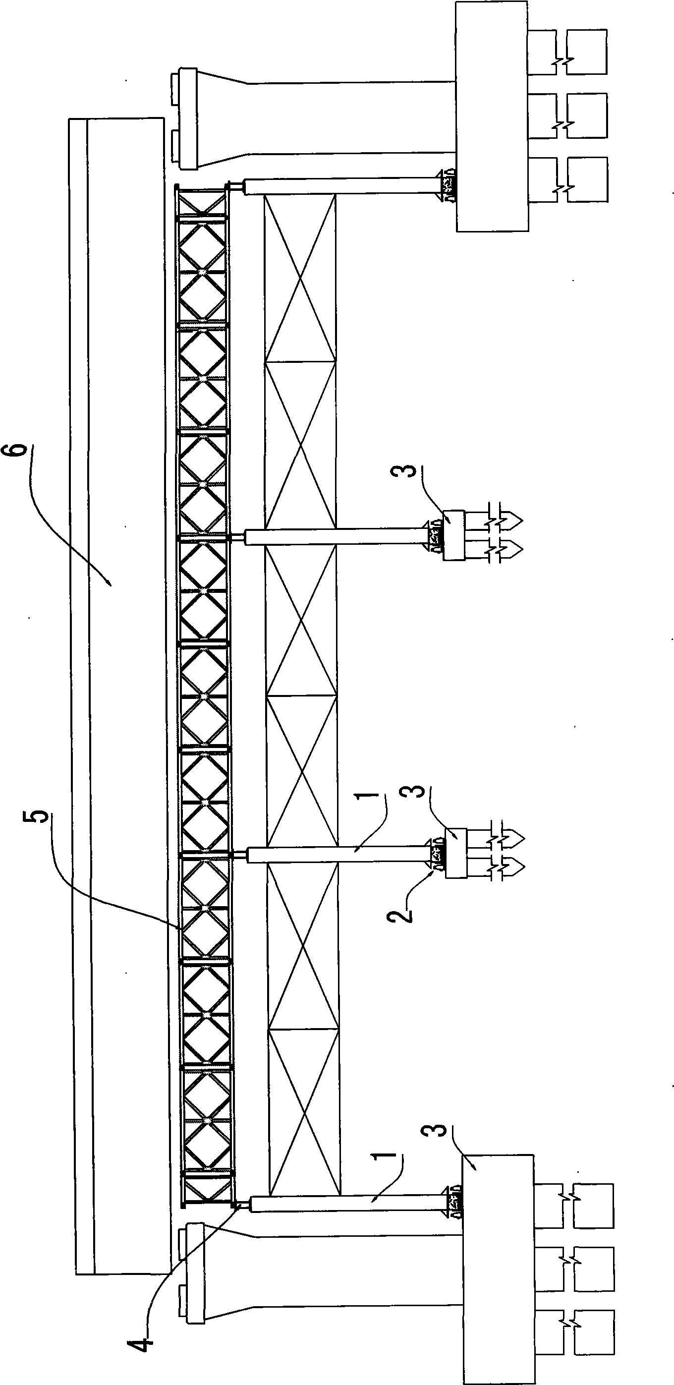
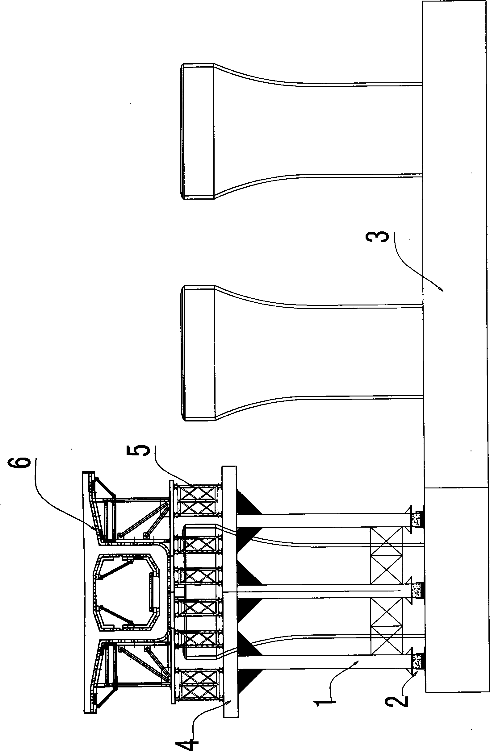
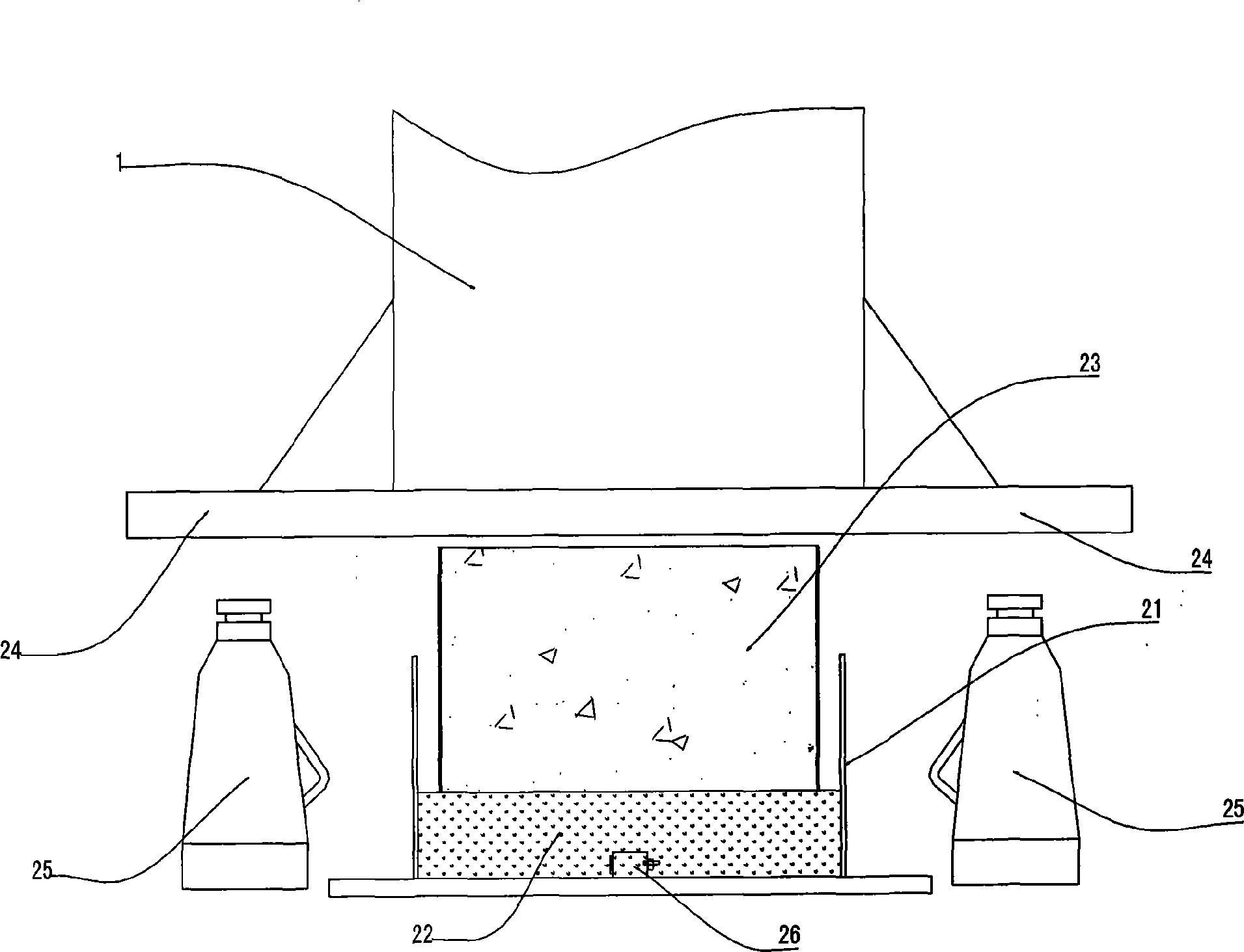
[0023] A beam-column support such as figure 1 , figure 2 , including a plurality of rows of columns 1, each column sits on the base part 3 for supporting it at the bottom through a liftable drop frame device 2, and the drop frame device is a sand bucket 21 with an openable and closed sand discharge port at the bottom, such as image 3 , the top of the sand bucket is open, sand 22 is housed in it, and there is a briquetting block 23 at the bottom of the column, which is placed in the sand bucket through the briquetting block and pressed on the sand in the sand bucket, and the bottom of the column is located at the position above the sand bucket. A flange 24 protrudes outward, and a hydraulic cylinder 25 is installed on the base part below the flange. The falling frame device can also be other widely used existing falling frame structures, which are prior art. The top of the column is equipped with a beam 4 and a longitudinal beam 5 to support the bridge mold 6 above it. The ...


PUM


Abstract

The invention discloses a beam-column type support and a method for constructing multi-section adjacent bridges using same. Upright posts of the beam-column type support are transversely and vertically connected into a whole in a fixed way and propped against a basic part which transversely runs through the pouring position of each bridge section by a support backout device. When pouring the multi-section adjacent bridges, the support, as a whole, can be moved transversely to the pouring position of each bridge section along the basic part; after the bridge sections in the same transverse rows are poured, the support, as a whole, can be moved to an access road which is on the side of the bridge and extends along the laying direction of the bridge; after being vertically moved to the position corresponding to the next pouring position of the bridge along the access road by a flat wagon, the support is transversely moved to the basic part which is on the bottom of each bridge section of the pouring position of the section, extends transversely and runs through the pouring position of each bridge; by transversely moving the support along the basic part, each bridge section of the pouring position of the section can be poured. In the method, the support can be moved transversely and vertically as a whole without dismounting, thus shortening the pouring construction period of the bridge and improving the construction efficiency.

Description

Technical field: [0001] The invention relates to a beam-column support for supporting bridge molds in the construction of cast-in-place beams and a method for using the support to construct multiple sections of adjacent bridges. Background technique: [0002] When the bridge is poured, it is necessary to use brackets to support the bridge mold, and the beam-column bracket is a form of bracket used more in bridge pouring. The existing beam-column support is mainly disassembled, which consists of a base part, a drop frame device, a column, a beam and a longitudinal beam. The column is supported on the base part by a drop frame device in the form of a sand bucket. Multiple rows of longitudinal beams are installed on the top, and the bridge mold is supported by criss-crossing beams and longitudinal beams to realize the support for bridge pouring. The bracket cannot be moved. After each section of the bridge is poured, the bracket needs to be completely disassembled and transpor...

Claims


Application Information

Patent Timeline
IPC IPC(8): E04G25/04
Inventor 张前军谢芳君刘忠新董启君于家顺
Owner 中铁二十二局集团第一工程有限公司
Why Eureka
Try Eureka