Eccentric shaft of side gauge device
A technology of eccentric shaft and side gauge, applied in the field of eccentric shaft, can solve the problems of easy wear, lower precision of side gauge, heavy maintenance workload, etc., and achieve the effect of prolonging service life, improving precision of drawing gauge, and reducing maintenance cost
Inactive Publication Date: 2012-02-01
ZHEJIANG WELLVAST PACKING PRINTING PRODS
View PDF0 Cites 0 Cited by
- Summary
- Abstract
- Description
- Claims
- Application Information
AI Technical Summary
Problems solved by technology
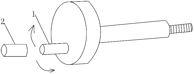
In use, it is found that both the copper sleeve 2 and the eccentric shaft 1 are prone to wear. The reason is that the copper sleeve and the eccentric shaft are made of different materials, the eccentric shaft is made of iron, and the friction coefficient of the eccentric shaft and the copper sleeve is relatively high. Large, it is difficult to accurately match the inner diameter of the copper sleeve and the outer diameter of the eccentric shaft
[0003] Under normal circumstances, it is necessary to replace the copper sleeve after one week of continuous work. The entire side gauge device needs to be disassembled when replacing the copper sleeve. To replace the copper sleeve, the entire side gauge must be disassembled, so it is very inconvenient to disassemble and assemble. The amount is also very large, which also reduces the accuracy of the side gauge
Method used
View moreImage
Smart ImageViewing Examples
Examples
specific Embodiment approach
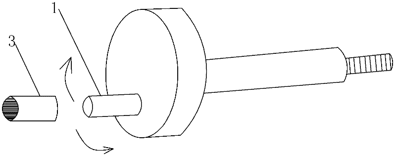
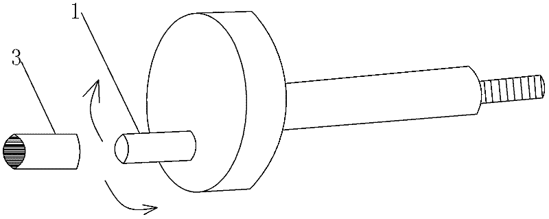
[0012] Example: Eccentric shafts for side gauge devices such as figure 2 As shown, the eccentric shaft body 1 is included, and a needle bearing 3 is sleeved on the eccentric shaft body 1, and the inner diameter of the needle bearing 3 is the same as the outer diameter of the eccentric shaft body.
Login to View More PUM
 Abstract
The invention discloses an eccentric shaft of a side gauge device. The eccentric shaft comprises an eccentric shaft body, wherein a needle roller bearing is sleeved on the eccentric shaft body, and the inner diameter of the needle roller bearing is same as the external diameter of the eccentric shaft body. According to the invention, the needle roller bearing with the external diameter close to that of a copper bush is used, the inner diameter of the needle roller bearing is same as the external diameter of the eccentric shaft body, and the lubrication degree of the needle roller bearing is far higher than that of the copper bush, so that friction is reduced, service life is greatly prolonged, and pull accuracy of the side gauge device is also improved; in normal condition, the eccentric shaft can be contentiously used for more than half a year, and under a better lubrication condition, the eccentric shaft can definitely work for one year, so that maintenance cost and complicated dismounting and mounting work load are both reduced.
Description
technical field [0001] The invention relates to a side gauge device in a gravure printing system, in particular to an eccentric shaft used for the side gauge device. Background technique [0002] The side gauge device includes an eccentric shaft assembly, such as figure 1 As shown, in work, the eccentric shaft is oscillating, and its oscillating angle is between 30 degrees and 45 degrees. For the needs of work, a copper sleeve 2 is set on the eccentric shaft. In use, it is found that both the copper sleeve 2 and the eccentric shaft 1 are prone to wear. The reason is that the copper sleeve and the eccentric shaft are made of different materials, the eccentric shaft is made of iron, and the friction coefficient of the eccentric shaft and the copper sleeve is relatively high. Large, it is difficult to accurately match the inner diameter of the copper sleeve and the outer diameter of the eccentric shaft. [0003] Under normal circumstances, it is necessary to replace the coppe...
Claims
Login to View More Application Information
Patent Timeline
 Patent Type & Authority Applications(China)
IPC IPC(8): B41F21/14
Inventor 李强王霄丹
Owner ZHEJIANG WELLVAST PACKING PRINTING PRODS
Features
- R&D
- Intellectual Property
- Life Sciences
- Materials
- Tech Scout
- Unparalleled Data Quality
- Higher Quality Content
- 60% Fewer Hallucinations
Learn More Browse by: Latest US Patents, China's latest patents, Technical Efficacy Thesaurus, Application Domain, Technology Topic, Popular Technical Reports.
© 2025 PatSnap. All rights reserved.Legal|Privacy policy|Modern Slavery Act Transparency Statement|Sitemap|About US| Contact US: help@patsnap.com


