Al technical title is built by PatSnap Al team. It summarizes the technical point description of the patent document.
A compressor and piston rod technology, applied in the field of compressors, can solve the problems of poor compression effect, inconvenient use, and complex structure of the compressor, and achieve the effect of simple structure, convenient use, and good effect
Active Publication Date: 2016-08-31
BENGBU JINPENG GAS EQUIP MFG
View PDF7 Cites 3 Cited by
Summary
Abstract
Description
Claims
Application Information
AI Technical Summary
This helps you quickly interpret patents by identifying the three key elements:
Problems solved by technology
Method used
Benefits of technology
Problems solved by technology
[0003] The existing compressor has poor compression effect, compl
Method used
Image
Click on the blue label to locate the original text in one second.
Reading with bidirectional positioning of images and text.
Examples
Embodiment Construction
[0036] It should be noted that, in the case of no conflict, the embodiments in the present application and the features in the embodiments can be combined with each other; the present invention will be described in detail below with reference to the accompanying drawings and in combination with the embodiments.
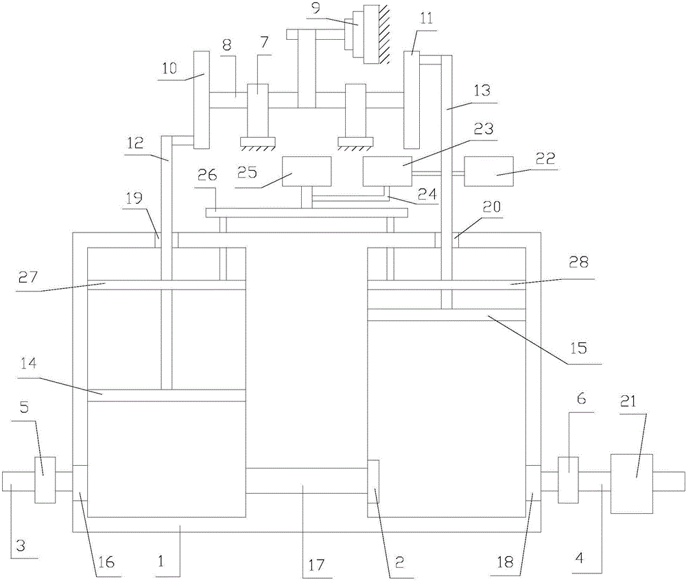
[0037] refer to figure 1 :
[0038] A two-stage compressor proposed by the present invention includes a housing 1, a membrane 2, a first connecting pipe 3, a second connecting pipe 4, a first one-way valve 5, a second one-way valve 6, a mounting frame 7, and a rotating shaft 8. Drive unit 9, first runner 10, second runner 11, first piston rod 12, second piston rod 13, first piston 14, second piston 15, heater 21, spray mechanism.
[0039] Housing 1 is provided with air inlet hole 16, connection hole 17, air outlet hole 18, first installation hole 19, second installation hole 20 on the top wall of housing 1, housing 1 is provided with first chamber, second Two caviti...
PUM
Abstract
The invention discloses a two-stage compressor which comprises a shell, a film, a first connecting pipe, a second connecting pipe, a first one-way valve, a second one-way valve, a mounting rack, a rotation shaft, a driving unit, a first runner, a second runner, a first piston rod, a second piston rod, a first piston and a second piston; an air inlet, a connecting hole and an air outlet are formed in the shell; a first mounting hole and a second mounting hole are formed in the top wall of the shell; a first accommodating cavity and a second accommodating cavity are formed in the shell; the air inlet, the connecting hole and the first mounting hole communicate with the first accommodating cavity; the connecting hole, the air outlet and the second mounting hole are communicated with the second accommodating cavity; the film is arranged in the second accommodating cavity; the first end of the film is hinged to the side wall of the shell; the second end of the film is a free end; one end of the first connecting pipe is connected with the air inlet; one end of the second connecting pipe is connected with the air outlet. The two-stage compressor is excellent in air compression effect.
Description
technical field [0001] The invention relates to the technical field of compressors, in particular to a two-stage compressor. Background technique [0002] As an important form of energy production, compressors are widely used in all aspects of life, especially in the fields of machinery, metallurgy, electronic power, medicine, packaging, chemical industry, etc., and become the mainstream product of compressed gas. [0003] The existing compressor has poor compression effect, complicated structure and inconvenient use, and needs to be further improved. Contents of the invention [0004] In order to solve the technical problems in the background technology, the present invention proposes a two-stage compressor with simple structure and good compression effect. [0005] A two-stage compressor, including a shell, a membrane, a first connecting pipe, a second connecting pipe, a first one-way valve, a second one-way valve, a mounting frame, a rotating shaft, a drive unit, a fir...
Claims
Application Information
Patent Timeline
Application Date:The date an application was filed.
Publication Date:The date a patent or application was officially published.
First Publication Date:The earliest publication date of a patent with the same application number.
Issue Date:Publication date of the patent grant document.
PCT Entry Date:The Entry date of PCT National Phase.
Estimated Expiry Date:The statutory expiry date of a patent right according to the Patent Law, and it is the longest term of protection that the patent right can achieve without the termination of the patent right due to other reasons(Term extension factor has been taken into account ).
Invalid Date:Actual expiry date is based on effective date or publication date of legal transaction data of invalid patent.