Heat exchanger

A technology of heat exchangers and heat exchange tubes, applied in the direction of heat exchange equipment, indirect heat exchangers, heat exchanger types, etc., which can solve the problems of reduced efficiency of assembly operations, increased number of parts, and high weight

Inactive Publication Date: 2009-09-16
SHOWA DENKO KK
View PDF5 Cites 14 Cited by
  • Summary
  • Abstract
  • Description
  • Claims
  • Application Information

AI Technical Summary

Problems solved by technology

[0011] However, in the conventional evaporator shown in the aforementioned Patent Document 1, the headers not related to heat exchange are arranged on the upper and lower sides, so that space and parts need to be installed accordingly, and there is a problem of causing high weight and large size.
[0012] Furthermore, although the evaporator shown in Patent Document 2 has a structure in which the header pipes are arranged only on the upper end side, each flat tube needs to be provided with a cover-shaped connecting member on the lower end side, which increases the number of parts and may cause assembly problems. Reduced operating efficiency, etc.
[0013] On the other hand, since the evaporator shown in Patent Document 3 is an evaporator using U-shaped flat tubes (heat exchange tubes), it is only necessary to assemble the headers to the upper end side, and it is possible to reduce the number of parts and achieve a small size. lightweight

Method used


Image

  • Heat exchanger
  • Heat exchanger
  • Heat exchanger

Examples


other Embodiment approach

[0239] (Pipe manufacturing apparatus of another embodiment)

[0240] Next, a manufacturing apparatus (manufacturing method) of another embodiment for manufacturing the heat exchange tube 2 described above will be described in detail.

[0241] In addition, in the following description of the pipe manufacturing apparatus, in order to facilitate understanding of the invention, the Figure 17 , the right side is referred to as "front side", the left side is referred to as "rear side", the upper side is referred to as "upper side", the lower side is referred to as "lower side", and the perpendicular direction is referred to as "left-right direction".

[0242] As shown in the figure, this heat exchange tube manufacturing apparatus (bending apparatus for flat tube members) has a pressing die 8 and a bending die 9 on a base frame 70 .

[0243] Such as Figure 17-2 0, the front end (rear end) of the pressing die 8 is provided with a mountain-shaped plate portion 81 that is in the sha...


PUM


Abstract

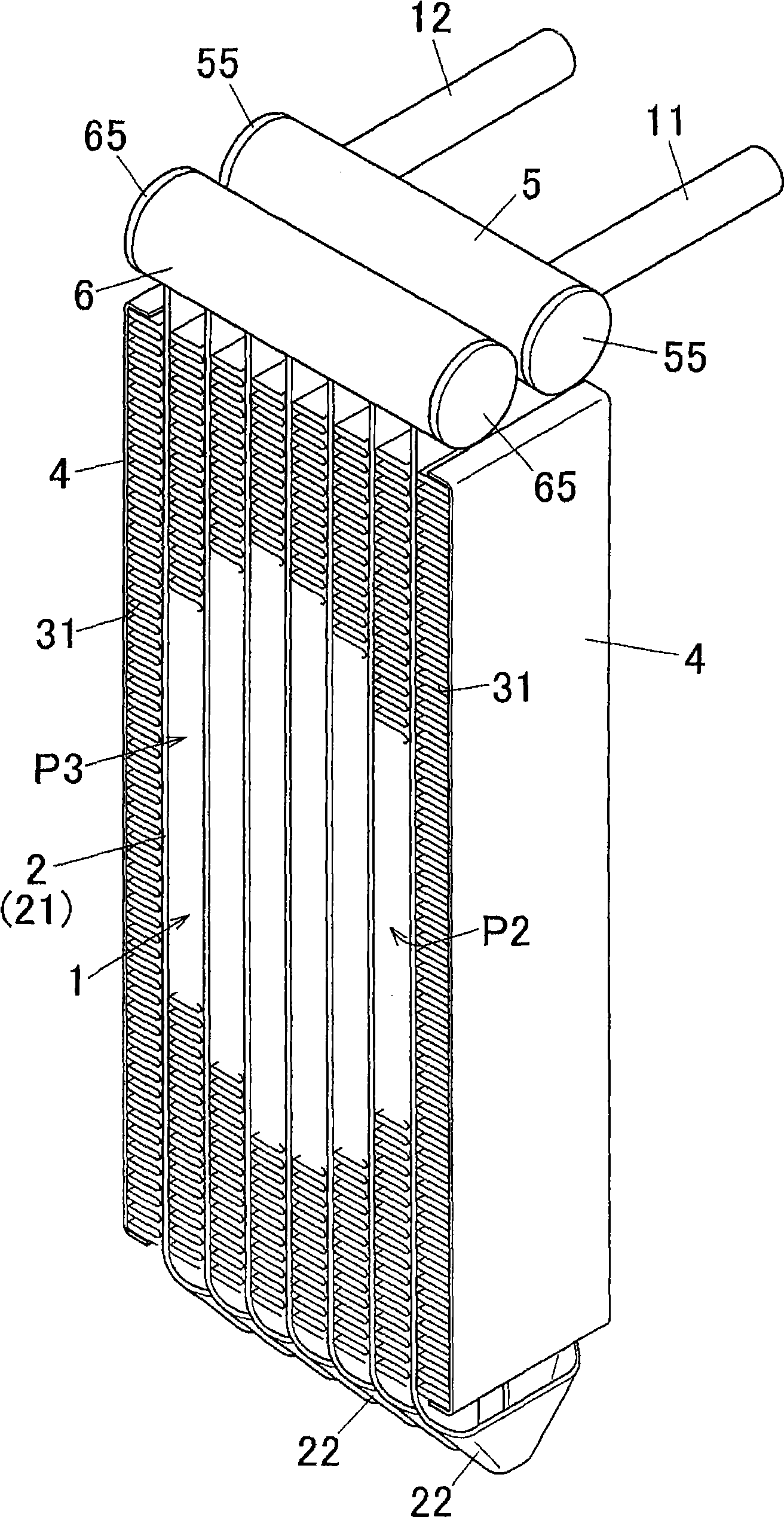
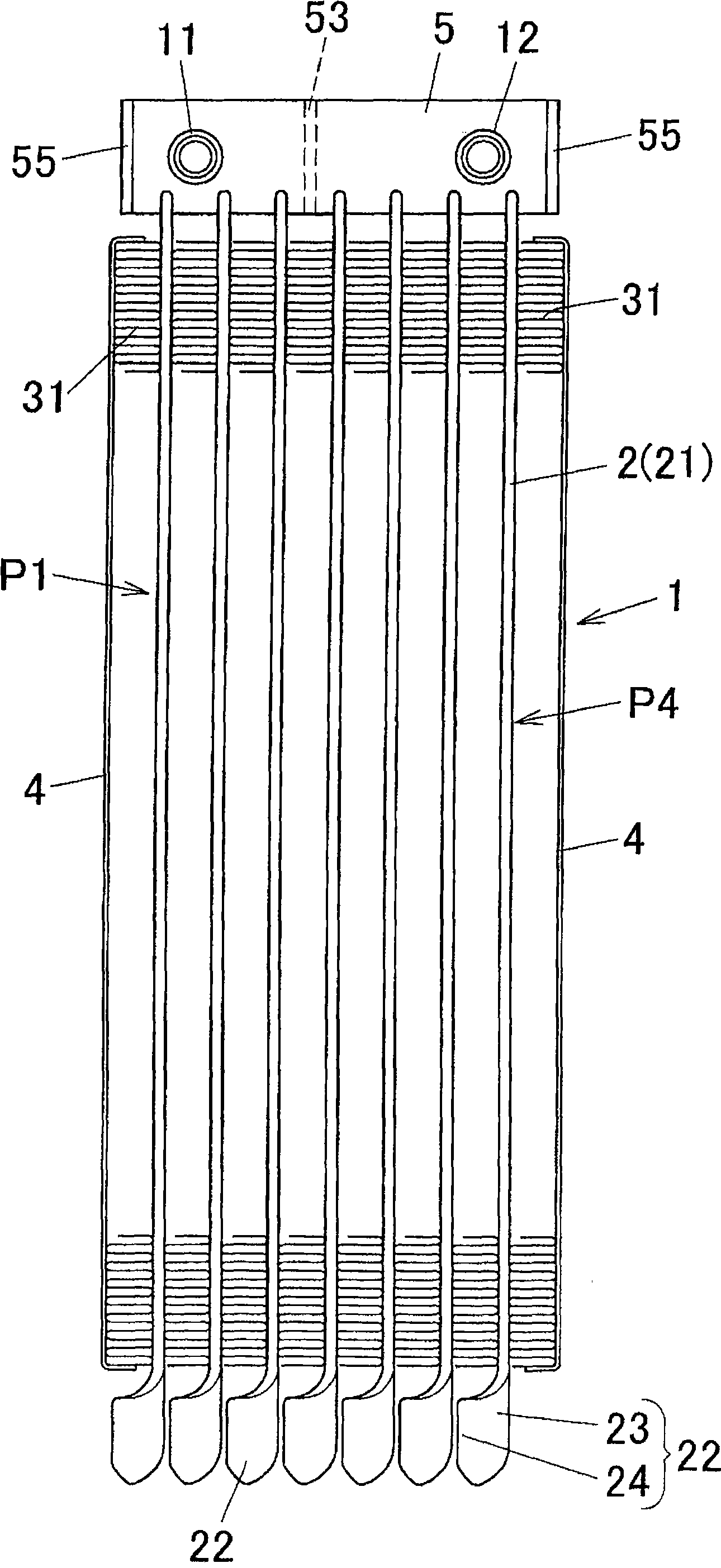
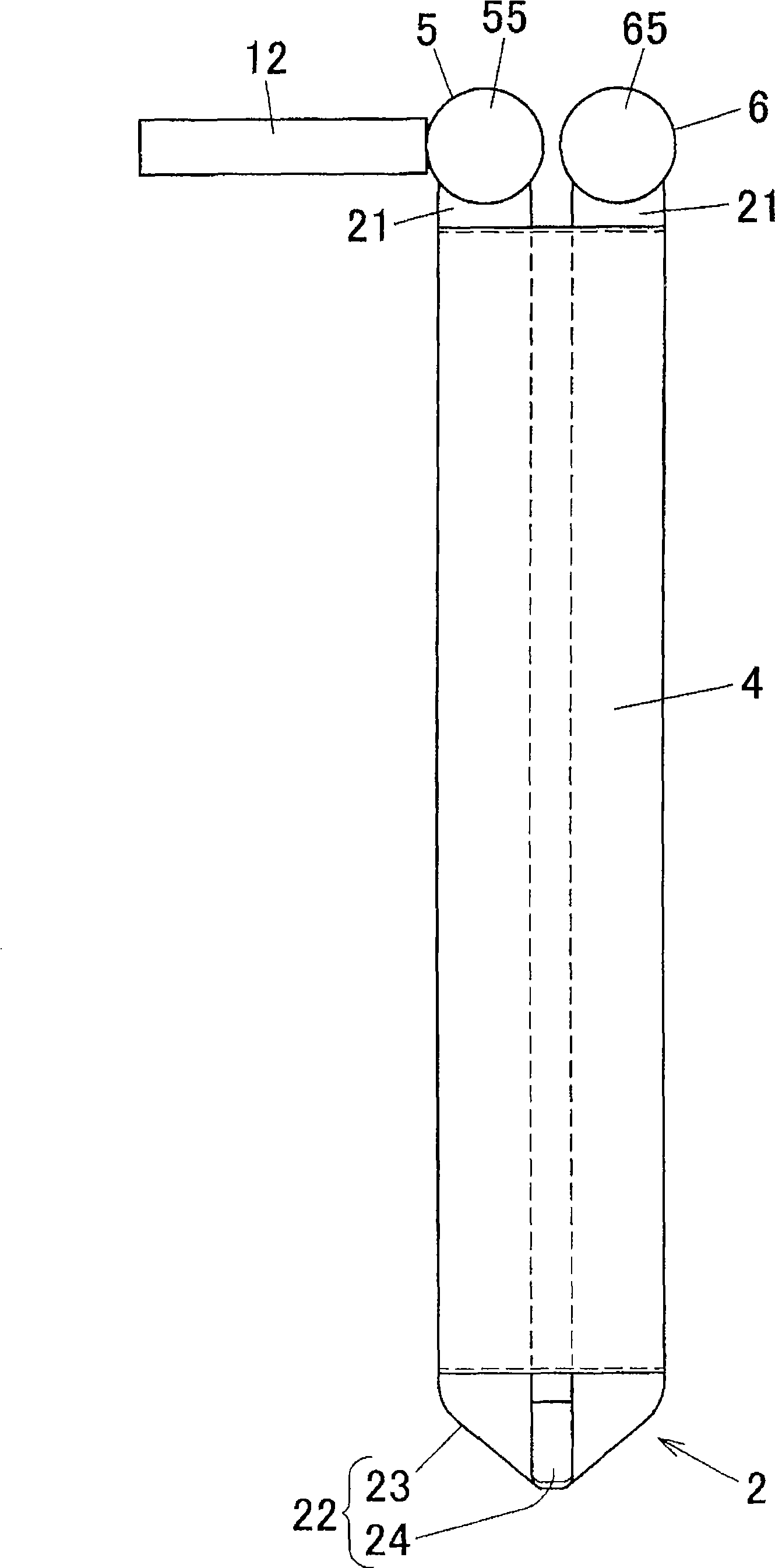
The present invention provides a heat exchanger, wherein a plurality of U-shaped heat-exchange tubes (2) are arranged along the tube thickness direction, the U-shaped heat-exchange tube has a pair of flat straight tube parts (21) in parallel in the width direction and a bending part (22) for communicating the pair of the straight tube parts (21). In the heat exchanger, the heat-exchange tube (2) is formed by bending two ends of a band-shaped flat tube component (20) angularly in an intermediate part which is used as the bending part (22), and the two ends of the flat tube component (20) is used as a pair of straight tube part (21). According to the heat exchanger of the invention, it is capable of reducing the component number and lightweighting.

Description

[0001] This application claims the priority of Japanese Patent Application No. 2008-60999 filed on March 11, 2008 and Japanese Patent Application No. 2008-126156 filed on May 13, 2008. The status forms part of this application. technical field [0002] The present invention relates to a heat exchanger used as, for example, an evaporator of a vehicle air conditioner or a room air conditioner, and related technologies. Background technique [0003] As an evaporator for a vehicle air conditioner or a room air conditioner, a stacked type evaporator in which a pair of disc-shaped plates are stacked together, or a heat exchange tube and a water tank (header) are mainly used. body, a header-type (tube-type) evaporator assembled by inserting a tube into a water tank, and the like. [0004] Among these evaporators, as header-type evaporators, for example, evaporators disclosed in the following Patent Documents 1 to 3 are known. [0005] In the evaporator disclosed in Patent Documen...

Claims


Application Information

Patent Timeline
Patent Type & Authority Applications(China)
IPC IPC(8): F28D1/04F28F1/02B21D11/00B21D53/02
CPCF28D1/0476F28F1/022
Inventor 岸正幸星野良一浅川高
Owner SHOWA DENKO KK
Why Eureka
Try Eureka