Continuously variable transmission

A technology of transmission and stepless speed change, which is applied in the direction of transmission, friction transmission, transmission control, etc. It can solve the problems of low energy efficiency rolling parts wear and excessive size, and achieve the effect of simplified coordinated control

Active Publication Date: 2014-04-09
ALLISON TRANSMISSION INC
View PDF4 Cites 0 Cited by
  • Summary
  • Abstract
  • Description
  • Claims
  • Application Information

AI Technical Summary

Problems solved by technology

Therefore, the selected traction load value will be too large for most cases, resulting in lower energy efficiency and premature wear of rolling parts

Method used


Image

  • Continuously variable transmission
  • Continuously variable transmission
  • Continuously variable transmission

Examples


Embodiment Construction

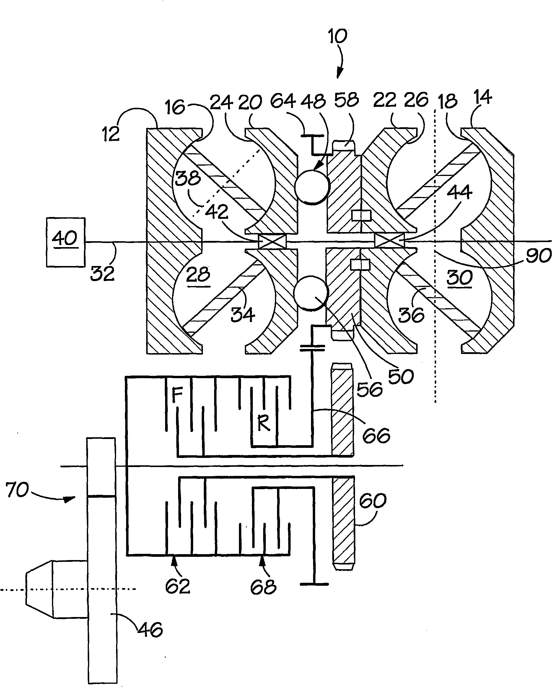
[0023] figure 1 A CVT using a toroidal raceway rolling traction type transmission 10 is shown. More specifically, this is a two-chamber full toroidal variator. The variator has a first input race 12 and a second input race 14 with respective semi-annular concave surfaces 16 , 18 . Between these input races are a first output race 20 and a second output race 22, and these two races also have respective semi-circular concave surfaces 24, 26 so that A first annular cavity 28 is formed between 12 and the first output raceway 20 , and a second annular cavity 30 is formed between the second input raceway 14 and the second output raceway 22 . These raceways have a common axis of rotation defined by a main shaft (schematically indicated at 32 ) around which they turn.

[0024] Each cavity 28 , 30 contains a respective roller set 34 , 36 . Each roller is mounted for rotation about a roller axis such as 38, and each roller moves on the toroidal surfaces of its associated input and o...


PUM


Abstract

The invention is concerned with control of a continuously variable vehicle transmission. The transmission in question is to have a variator (10) which is coupled between a rotary transmission input (32) and a rotary transmission output (46), to provide continuous variation in a transmission dive ratio, via a launch device such as a clutch (62; 68). The variator and the launch device are constructed and arranged to exert a required torque, defined by an input signal. In accordance with the invention, the same control signal is used to control both the variator torque and the torque capacity of the launch device. In such an arrangement, vehicle launch (i.e. moving away from rest) can be controlled in a straightforward manner by progressively raising the relevant control signal, preferably a hydraulic pressure signal. Further independent claims are including for applying traction load to races (20, 22) of the variator and for a method setting torque of the launch device (62; 68) higher than torque of the variator (10).

Description

technical field [0001] The present invention relates to a continuously variable transmission (continuously variable transmission, continuously variable transmission). One aspect of the invention relates to the control of a launch device and a variator in such a transmission. Background technique [0002] In any continuously variable transmission device, there is a device for continuously changing the transmission ratio. Such a device is referred to herein as a "transmission". [0003] In a vehicle transmission, preparations must be made for "launch" (ie, accelerating the vehicle out of a standing start). In this regard, some transmissions rely on the use of a "starter" such as a clutch. The clutch is used to decouple the engine from the driven wheels when the vehicle is stationary. To move the vehicle away from a standing start, put the transmission in a low gear, set the engine to produce the proper torque, and gradually engage the engine, increasing the speed of the dr...

Claims


Application Information

Patent Timeline
Patent Type & Authority Patents(China)
IPC IPC(8): B60W10/101F16H61/02B60W10/02F16H61/664B60W30/18
CPCF16H37/021F16H15/38F16H2061/661B60W2710/105B60W10/02B60W2710/027F16H61/6649B60W30/18027B60W30/18F16H61/664
Inventor 克里斯托弗·约翰·格林伍德
Owner ALLISON TRANSMISSION INC
Why Eureka
Try Eureka