Improving image masks

An image and mask technology, applied in the field of graphics and image processing, can solve problems such as incomplete inclusion, and achieve the effect of improving accuracy

Active Publication Date: 2009-09-16
ADOBE INC
View PDF1 Cites 20 Cited by
  • Summary
  • Abstract
  • Description
  • Claims
  • Application Information

AI Technical Summary

Problems solved by technology

However, these techniques may produce opacity masks that do not completely cover the desired area

Method used


Image

  • Improving image masks
  • Improving image masks
  • Improving image masks

Examples


Embodiment Construction

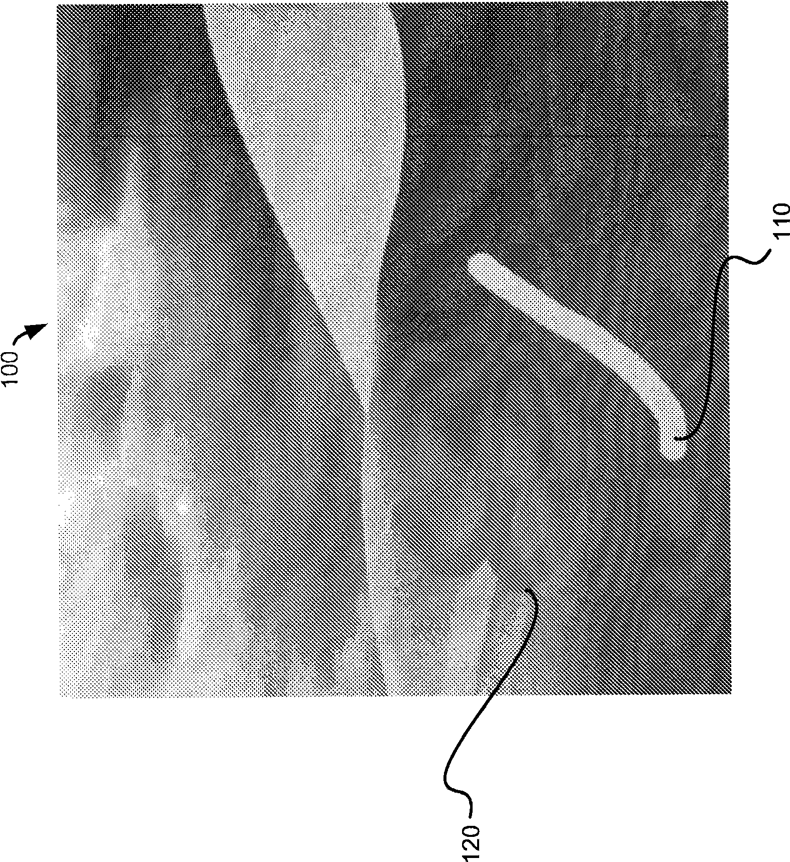
[0028] figure 1 An image 100 is shown with a foreground stroke 110 and a background stroke 120 . In general, an image can be represented by a raster of pixels (eg, a two-dimensional array of pixels), where each pixel encodes a value (eg, color, brightness, or both) describing the image at a particular location. Color images are usually specified in terms of specific color spaces (for example, RGB, CMYK, CIELAB, CIE XYZ, CIE LUV, YCC, YIQ, HSB, HSL, grayscale, or black and white), which determine how each The pixel's value is interpreted as a color. For example, in an RGB-encoded image, each pixel is encoded by at least three values ​​corresponding to each of the three RGB color components (red, green, and blue). In a grayscale image, colors correspond to levels of lightness, or shades of gray. In a black and white image, the color is either white or black.

[0029] Typically, an image and its constituent pixels are described and stored by a file having an image format such...


PUM


Abstract

Methods, systems, and apparatus, including computer program products, feature receiving an image mask (1020) where the image mask identifies a first opacity value of pixels in a raster image (1010). The first opacity value ranges between a value representing foreground and a value representing background. Each pixel in the image has a color. A first boundary pixel is identified in the image. A second opacity value for the first boundary pixel is determined using a first local color model of opacity. The first local color model of opacity is determined based on the colors of the pixels in the image within a local neighborhood of the first boundary pixel.

Description

technical field [0001] The present disclosure relates to graphics image processing, and more particularly, to selecting portions of an image. Background technique [0002] Typically, for each pixel in an image, an image mask indicates whether each pixel is selected or not. Image mattes are sometimes called image mattes, selection masks, or alpha channels. A binary mask is an image mask that can be used to indicate one of two mutually exclusive states (selected or not selected, foreground or background, etc.) for each pixel. Opacity masks (also sometimes called progressive opacity masks) are image masks that indicate the degree to which each pixel is in one of two mutually exclusive states. An opacity mask can be used, for example, to indicate that some pixels are entirely foreground or entirely background, while other pixels are mostly foreground with a bit of background. The degree to which a given pixel is defined as foreground by the opacity mask may be referred to as ...

Claims


Application Information

Patent Timeline
Patent Type & Authority Applications(China)
IPC IPC(8): G09G5/02
CPCG06T2210/62G06T15/503
Inventor G·D·威伦斯基
Owner ADOBE INC
Why Eureka
Try Eureka