
Gluewater-defoaming device and defoaming method

A technology of glue and glue water pressure, applied in separation methods, chemical instruments and methods, foam dispersion/prevention, etc., can solve the problems of unavoidable, difficult, and unequal mixing ratios, preventing the entry of outside air, and the structure of the device is simple. , to meet the effect of mass production

Inactive Publication Date: 2009-09-23
HENAN KAIRUI DIGITAL
View PDF0 Cites 9 Cited by
  • Summary
  • Abstract
  • Description
  • Claims
  • Application Information

AI Technical Summary

Problems solved by technology

In the original glue defoaming method, a chemical remover is often used to eliminate air bubbles. The disadvantages of this method are: first, the remover can only be used to eliminate bubbles on the surface of the glue solution. Bubbles, because of their small buoyancy, are difficult to float to the surface of the solution and cannot be eliminated; the second is that the elimination agent is left in the glue solution, which will cause the deterioration of the glue solution and form fine granular particles, which will affect the surface quality and quality of the glue product. Gloss
Vacuuming may remove the volatile components in the hardener and make the final mixing ratio wrong. It may also cause a layer of film to form on the surface of the glue and prevent the internal air bubbles from escaping.
In addition, when the volume of the glue bucket is large, it is difficult to remove the air bubbles at the bottom of the bucket in a short time by vacuuming; Unable to meet the needs of normal production

Method used


Image

  • Gluewater-defoaming device and defoaming method
  • Gluewater-defoaming device and defoaming method
  • Gluewater-defoaming device and defoaming method

Examples


Embodiment Construction

[0017] Embodiments of the present invention will now be described with reference to the drawings, in which like reference numerals represent like elements.

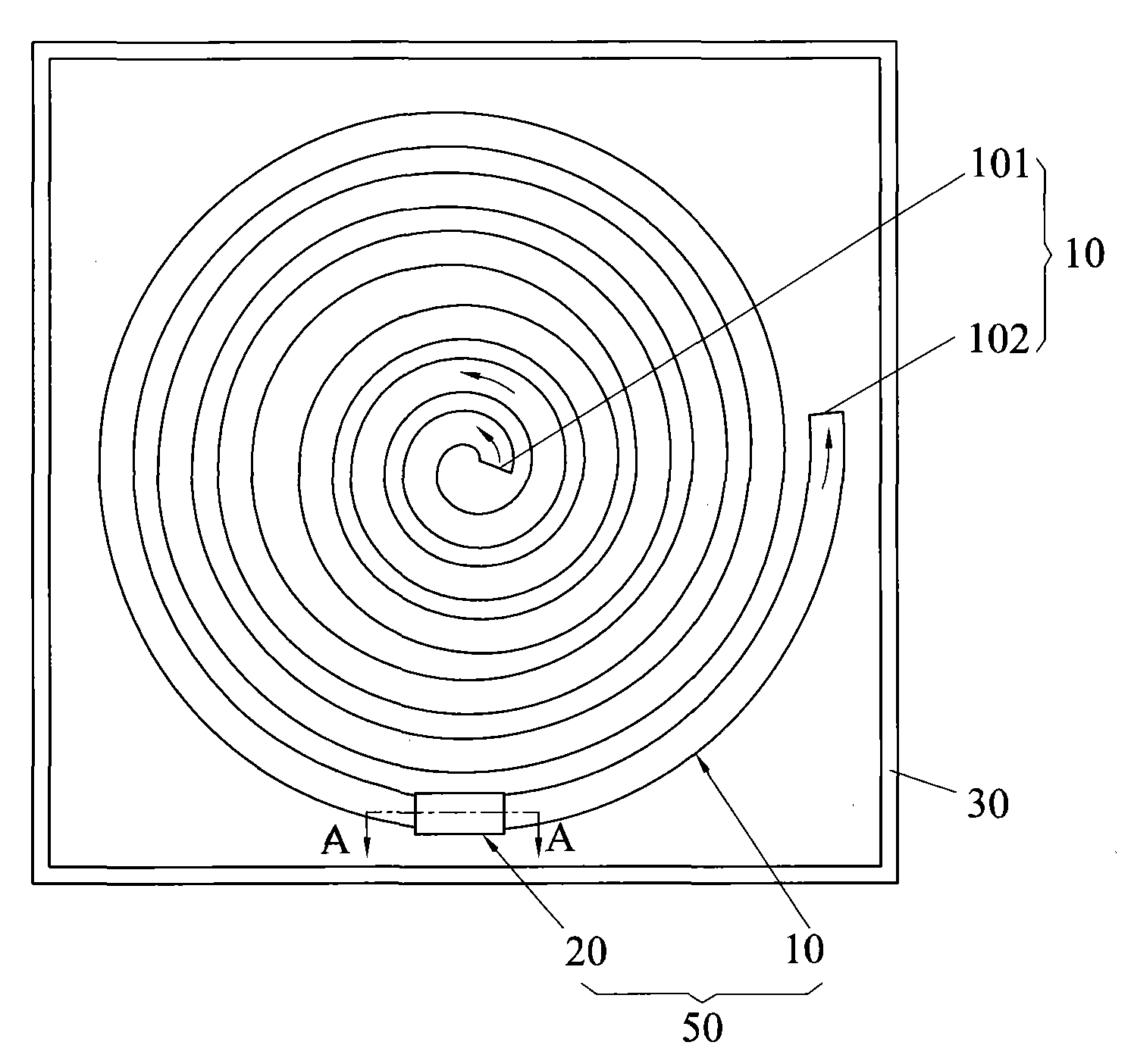
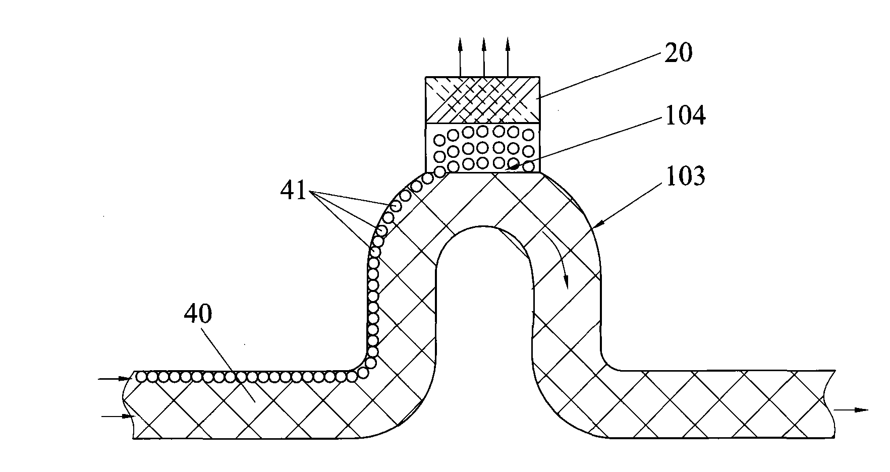
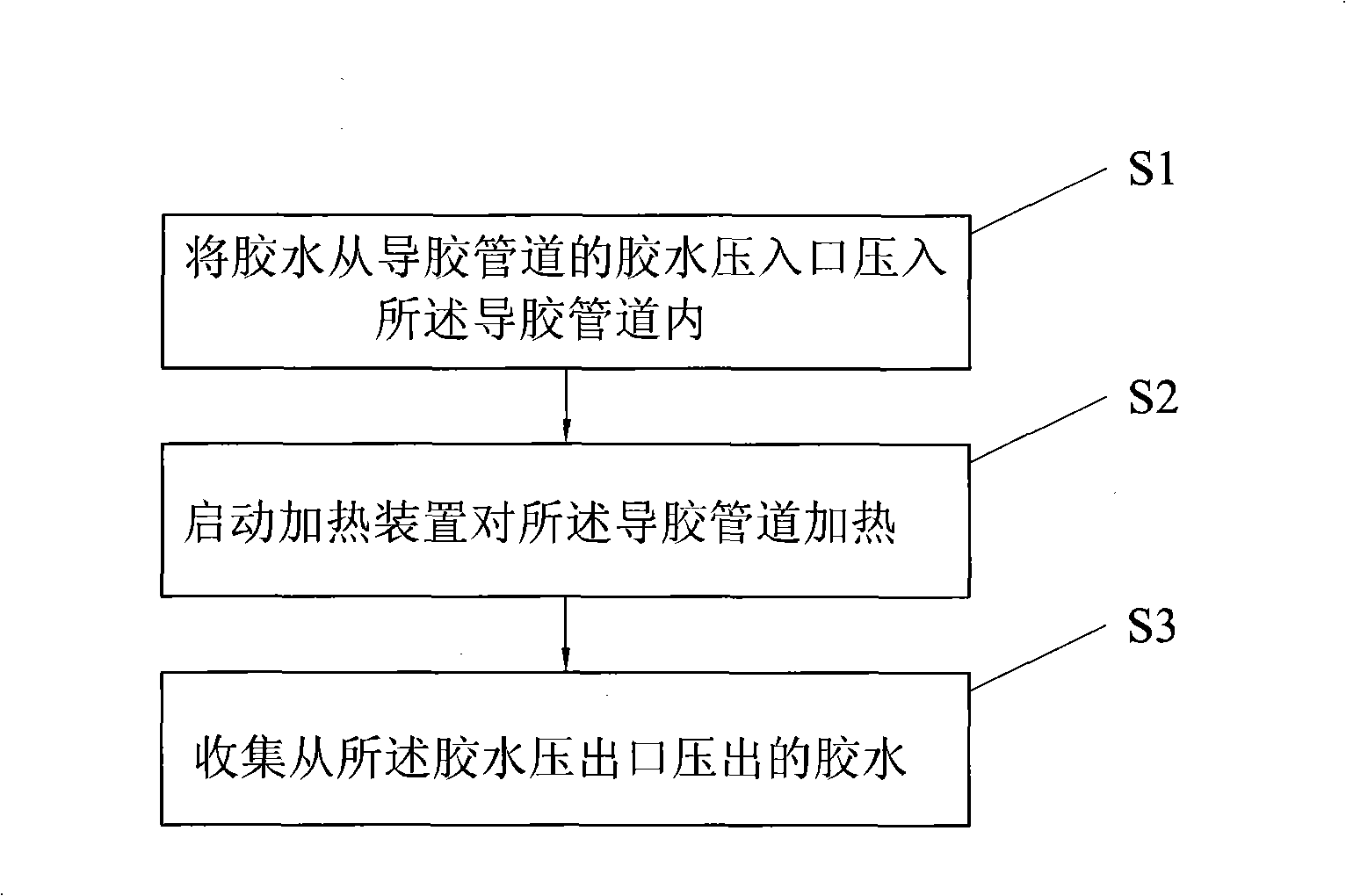
[0018] Such as figure 1 and figure 2 As shown, the glue defoaming device of the present invention includes a heating device (not shown) and a container 30, the heating device is installed on the container 30, the heating device is electrically connected to the outside, and it also includes a defoaming device Mechanism 50, the defoaming mechanism 50 includes a glue guiding pipeline 10 and a filter device 20, the glue guiding pipeline 10 has a glue pressure inlet 101 and a glue pressure outlet 102, and the glue pressure outlet 102 end of the glue guiding pipeline 10 has a curved A raised arched circuit 103 is folded, and a foam discharge port 104 is opened on the raised arched circuit 103, and the filter device 20 is arranged at the foam discharge port 104 of the raised arched circuit 103, The glue guiding pipe 10 is acc...


PUM


Abstract

The invention discloses a gluewater-defoaming device which comprises a heating device, a container and a defoaming mechanism, wherein the defoaming mechanism comprises a gluewater-guiding pipeline and a filter device, and the gluewater-guiding pipeline is provided with a gluewater-pressing inlet and a gluewater-pressing outlet which is provided with a bending protruding arc loop with a defoaming opening; the filter device is arranged at the defoaming opening of the protruding arc loop, and the gluewater-guiding pipeline is contained in the container; and gluewater is pressed in the gluewater-guiding pipeline to heat the whole gluewater-guiding pipeline so that foam contained in the gluewater gradually floats up above the inner wall of the gluewater-guiding pipeline and is discharged from the filter device at the defoaming opening while the gluewater flows by the defoaming opening arranged on the arc loop, therefore, the defoaming effect is favorable and the requirement for mass production is satisfied. The device has simple structure and is convenient to transplant to the prior various technological equipment. In addition, the invention also discloses a gluewater-defoaming method using the gluewater-defoaming device.

Description

technical field [0001] The invention relates to a glue defoaming device and a defoaming method, in particular to a device and a method suitable for eliminating bubbles in glue used for bonding during optical disk production. Background technique [0002] With the continuous increase of people's demand for information, the inherent storage space has long been unable to meet the requirements, and the strong social demand has prompted the rapid development of optoelectronic technology. Since the advent of optical discs, due to their advantages of high storage density, small size, long storage period, low cost, high compatibility and low error rate, they have become the mainstream of optical information recording media and one of the most popular optical storage media. one. Technically speaking, optical discs are intended to cover home entertainment, computers, and business information in a single digital format. They are a relatively new generation of storage technology with l...

Claims


Application Information

Patent Timeline
Patent Type & Authority Applications(China)
IPC IPC(8): B01D19/02
CPCB01D19/02B01D19/0057
Inventor 范继良杨明生罗文超
Owner HENAN KAIRUI DIGITAL
Learn More