Improved structure of dyeing machine

A printing and dyeing machine and unit technology, applied in textile processing machine accessories, textiles and papermaking, textile material processing, etc., can solve problems such as belt loss of elasticity, affecting the quality of printing and dyeing products, and inability to print and dye transmission at the same time

Inactive Publication Date: 2011-10-26
张朝宗
View PDF0 Cites 0 Cited by
  • Summary
  • Abstract
  • Description
  • Claims
  • Application Information

AI Technical Summary

Problems solved by technology

[0002] Conventional printing and dyeing machines are generally unable to print and dye at the same time during the lifting process, which makes it impossible to use time reasonably and improve efficiency; moreover, even if it can be driven, only one end of the belt is lifted, causing the belt to become too tired and lose its elasticity, thereby affecting the quality of printing and dyeing products.

Method used


Image

  • Improved structure of dyeing machine
  • Improved structure of dyeing machine
  • Improved structure of dyeing machine

Examples


Embodiment Construction

[0012] The present invention will be described in further detail below in combination with specific embodiments.

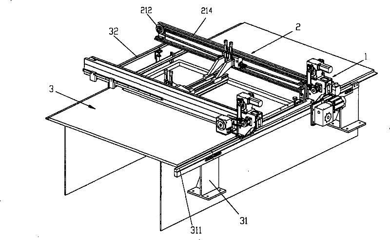
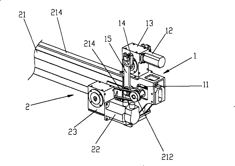
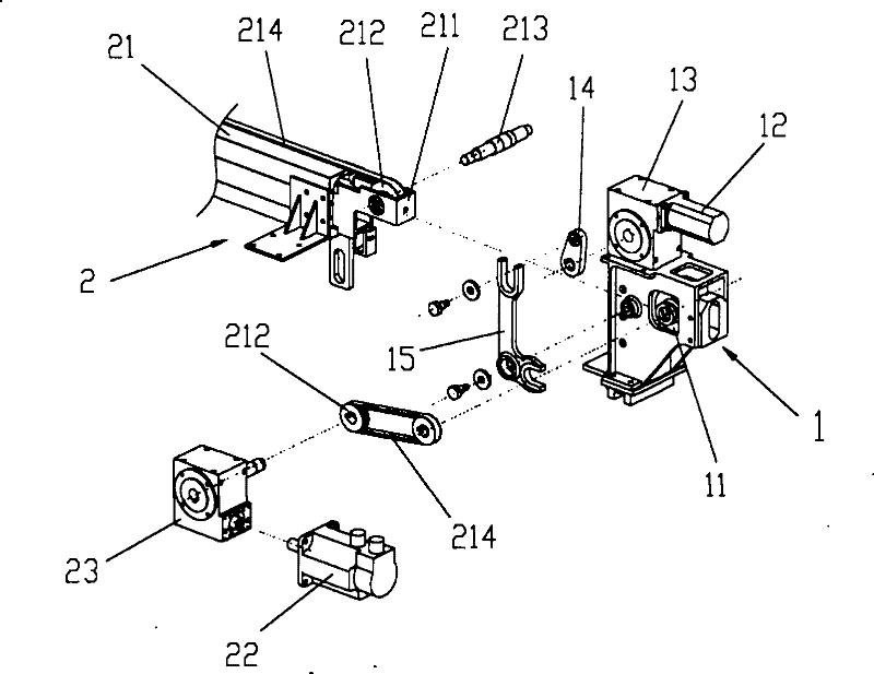
[0013] As shown in Figures 1 to 5, the structure of the printing and dyeing machine provided by the present invention mainly includes:

[0014] A lifting unit 1, the lifting unit 1 is provided with a lifting slot 11:

[0015] A lifting motor 12, the motor 12 is mounted on the lifting unit 1 and connected to the reducer 13;

[0016] A speed reducer 13, and a swing rod 14 protrudes from both sides of the speed reducer 13;

[0017] A swing lever arm 15, the swing lever arm 15 is pivotally arranged on the elevator unit 1, one end is connected to the swing lever 14, and the other end is inserted into the transmission rod 214 of the printing and dyeing track 21;

[0018] A printing and dyeing unit 2, the printing and dyeing unit 2 is provided with a printing and dyeing track 21;

[0019] A printing and dyeing track 21, one end of the printing and dyeing track 21 is p...


PUM


Abstract

The invention relates to an improved structure of a dyeing machine, which mainly comprises a lifting unit and a dyeing unit, wherein, the lifting unit is provided with a lifting groove; a motor and a reducer are arranged on the lifting unit; a swinging lever is arranged outside the two sides of the reducer and moveably connected with a swaying lever arm; the dyeing unit is provided with a dyeing rail, and driving wheels are arranged at the two ends of the dyeing rail; a driving belt is sleeved on the driving wheel; a driving rod is arranged at one end of the dyeing rail and sleeved in the lifting groove of the lifting unit; the driving wheel is sleeved outside the driving rod and in transmission connection with the motor via the reducer; and the motor drives the lifting unit to conduct the single-sided lifting displacement and simultaneously drives the dyeing unit to lift together with the lifting unit and conduct the dyeing operation on a transmission basis. The design of the dyeing machine can simplify the structure, so that the dyeing belt is not prone to elastic fatigue; and the design thereof can reduce the production cost of the dyeing machine and improve the quality and efficiency of the dyeing products, thereby achieving the purpose of high practicability.

Description

technical field [0001] The invention relates to the structure of a printing and dyeing machine, in particular to an improved structure in which the printing and dyeing transmission and the lifting transmission of the printing and dyeing machine are integrated. Background technique [0002] Conventional printing and dyeing machines are generally unable to print and dye at the same time during the lifting process, which makes it impossible to use time reasonably and improve efficiency; moreover, even if it can be driven, only one end of the belt is lifted, causing the belt to become too tired and lose its elasticity, thereby affecting the quality of printing and dyeing products. Contents of the invention [0003] The present invention aims at the above-mentioned defects of the prior art, and provides a printing and dyeing machine structure, the main purpose of which is to effectively solve the lack of belt fatigue caused during the lifting process, and has great practicabilit...

Claims


Application Information

Patent Timeline
Patent Type & Authority Patents(China)
IPC IPC(8): D06B23/00D06B23/20
Inventor 李清忠
Owner 张朝宗
Why Eureka
Try Eureka