Energy-dissipating and collision-preventing combined device of floating composite pier
A composite material and anti-collision device technology, applied in road safety devices, bridges, bridge parts, etc., can solve the problems of heavy weight, inconvenient maintenance and replacement, poor corrosion resistance, etc. Guaranteed effect
Inactive Publication Date: 2010-11-10
NANJING TECH UNIV
View PDF0 Cites 0 Cited by
- Summary
- Abstract
- Description
- Claims
- Application Information
AI Technical Summary
Problems solved by technology
The purpose of the present invention is to design a light weight, good corrosion resistance, light weight and Energy-dissipating and anti-collision device for floating composite pier with easy replacement
Method used
View moreImage
Smart ImageViewing Examples
Examples
Embodiment Construction
Login to View More PUM
 Abstract
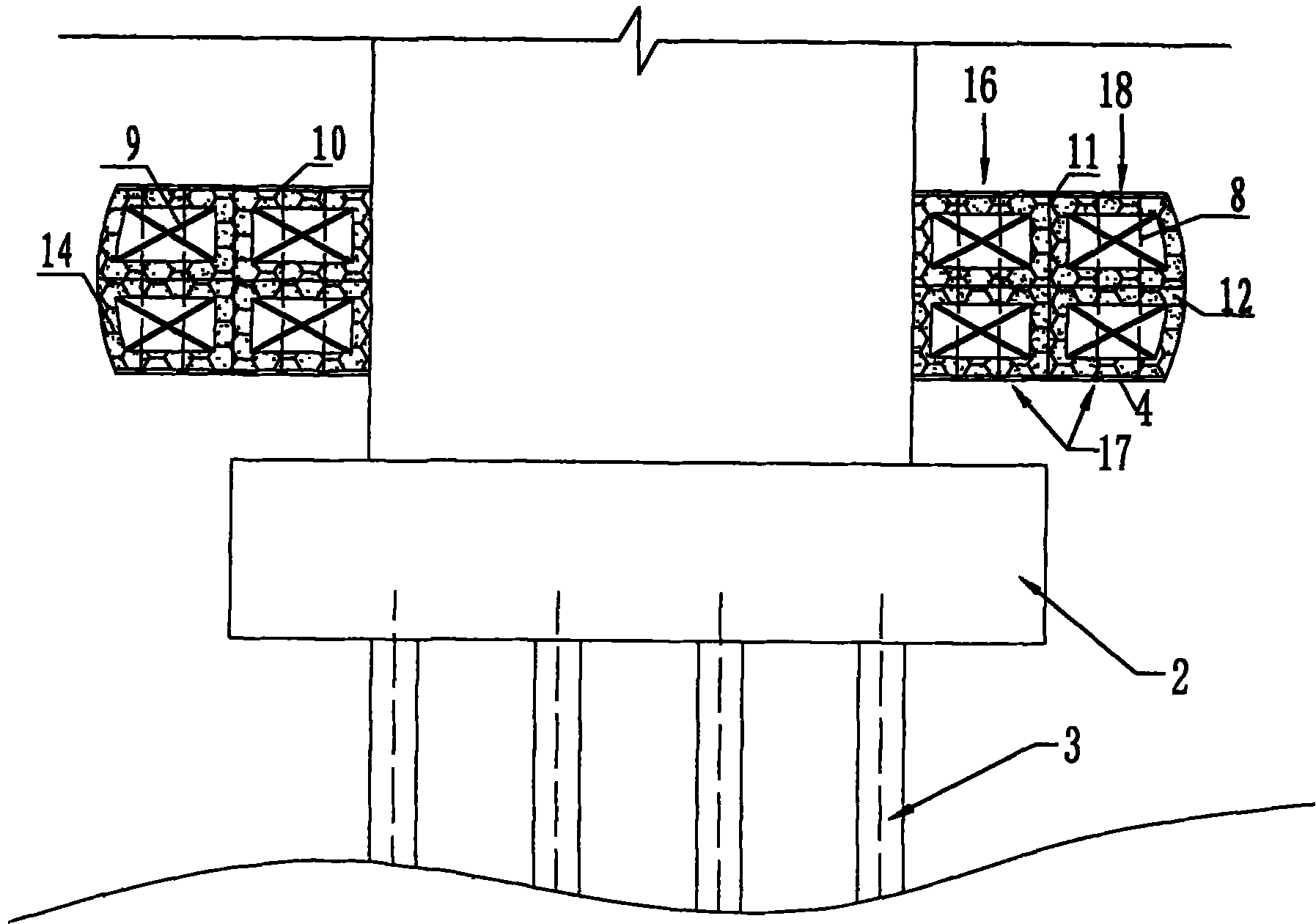
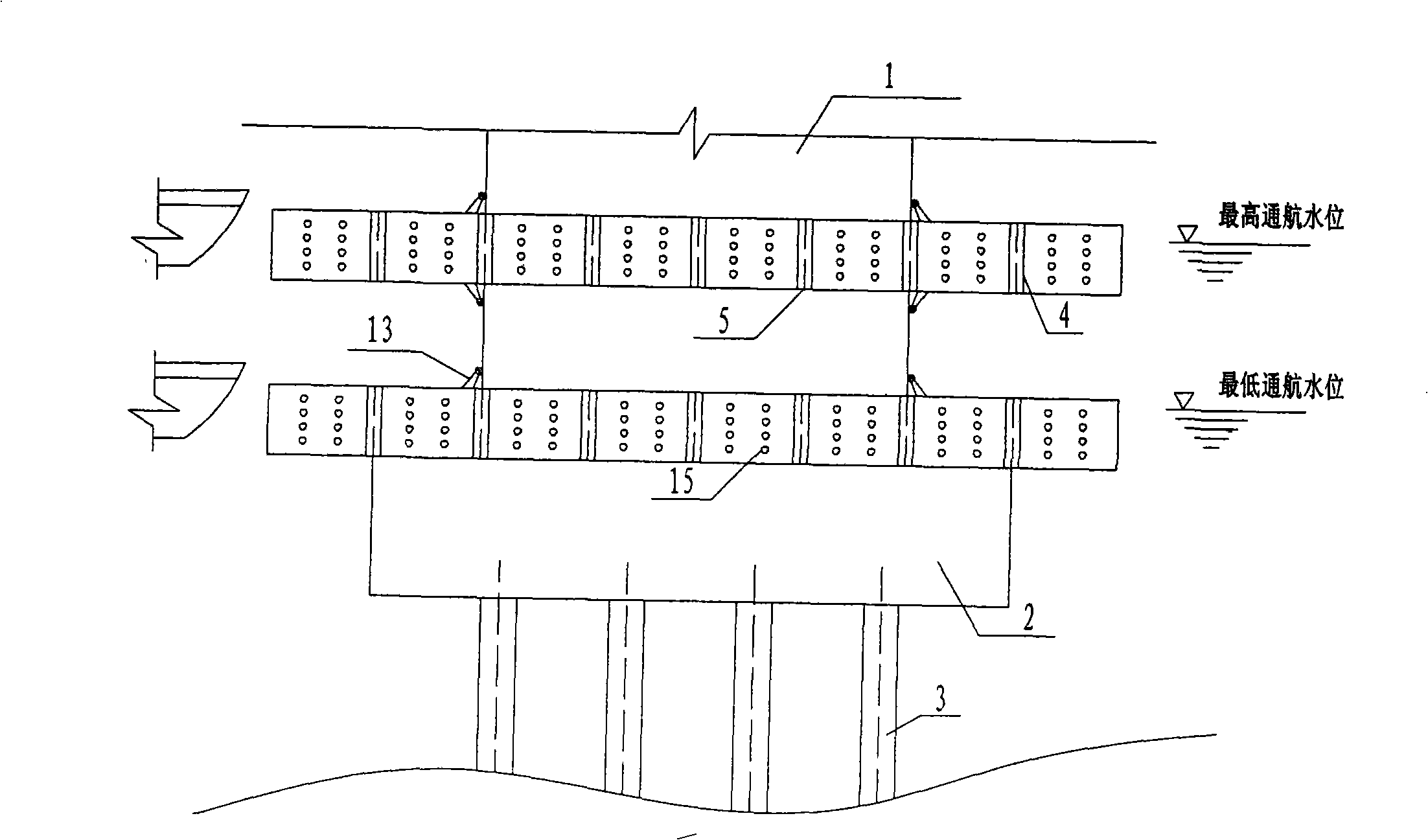
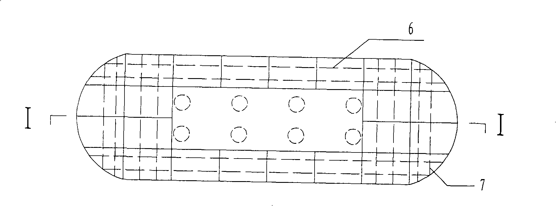
The invention relates to an energy-dissipating and collision-preventing combined device of a floating composite pier, which is characterized by at least comprising an internal layer corrosion-preventing ring (16) arranged along the pier, wherein the internal layer corrosion-preventing ring (16) comprises a plurality of composite lattice pouring jackets (17) arranged around the pier, the compositelattice pouring jackets (17) are connected to form an integrated structure through longitudinal composite presstressed reinforcing steels (6) and transverse composite presstressed reinforcing steels (7), the side of each composite lattice pouring jacket (17) is provided with an anchor head (10), the upper surface and the lower surface of each composite lattice pouring jacket (17) are both embedded with embedding pieces (11) connected with the adjacent composite lattice pouring jackets (17); part or all of the composite lattice pouring jackets (17) forming the internal layer corrosion-avoidingring (16) are connected with pulleys (13); the joint of the adjacent composite lattice pouring jackets (17) is provided with a sealing body; and one surface of each composite lattice pouring jacket (17) contacting with water is provided with a wave-dissipating hole (15). Compared with the traditional steel pouring jacket, the invention has better shock resistance and durability, light weight, andconvenient installation and repair, can save materials, and shorten the construction period.
Description
Floating Composite Pier Energy Dissipation Anti-Collision Combined Device technical field The invention relates to an infrastructure, especially a protective structure of bridges in water, in particular to a floating composite material pier energy dissipation and anti-collision combination device. Background technique As we all know, with the continuous development of transportation, a large number of bridges across the sea and across the river are constantly being built. For bridges spanning waterways, it is inevitable to bear the risk of ship collision. Such incidents often cause loss of bridge structure, service life, safety and earthquake resistance, and even cause catastrophic consequences such as bridge destruction and death. The cost of rebuilding bridges and dredging waterways is also very alarming. The existing anti-collision devices for navigable bridges mostly use steel casings on the periphery of the bridge piers. The main function of the anti-collision steel ...
Claims
Login to View More Application Information
Patent Timeline
 Patent Type & Authority Patents(China)
IPC IPC(8): E01F15/14E01D19/02E02B3/26E02B3/20
CPCY02A30/30
Inventor 刘伟庆王俊方海
Owner NANJING TECH UNIV
Features
- R&D
- Intellectual Property
- Life Sciences
- Materials
- Tech Scout
- Unparalleled Data Quality
- Higher Quality Content
- 60% Fewer Hallucinations
Learn More Browse by: Latest US Patents, China's latest patents, Technical Efficacy Thesaurus, Application Domain, Technology Topic, Popular Technical Reports.
© 2025 PatSnap. All rights reserved.Legal|Privacy policy|Modern Slavery Act Transparency Statement|Sitemap|About US| Contact US: help@patsnap.com


