
LED illumination device

A technology of light-emitting diodes and lighting devices, which is applied in lighting devices, cooling/heating devices of lighting devices, lighting and heating equipment, etc., and can solve problems such as limited lighting angles, inability to illuminate lighting devices at the same time, and poor lighting effects. Achieve the effect of large lighting area and high heat dissipation efficiency

Inactive Publication Date: 2012-05-16
CHAMP TECH OPTICAL FOSHAN +1
View PDF4 Cites 1 Cited by
  • Summary
  • Abstract
  • Description
  • Claims
  • Application Information

AI Technical Summary

Problems solved by technology

[0004] However, since these light-emitting diodes are located on the same side of the heat sink, the light emitted by them can only radiate outward from this side of the heat sink, and the light angle is limited, so they cannot illuminate the surroundings of the lighting device at the same time, and the lighting effect is not good.

Method used


Image

  • LED illumination device
  • LED illumination device
  • LED illumination device

Examples


Embodiment Construction

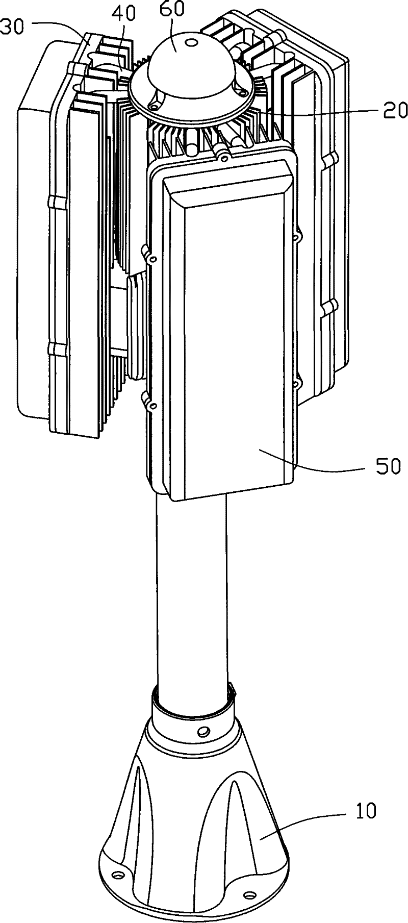
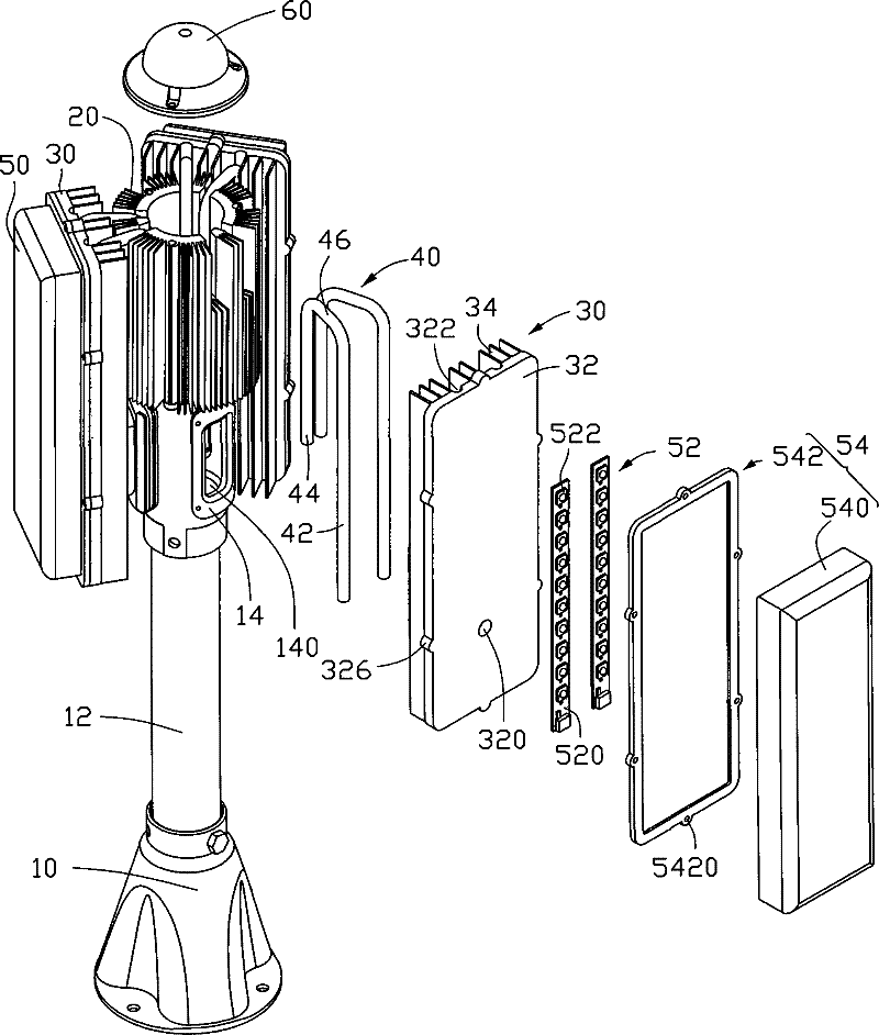
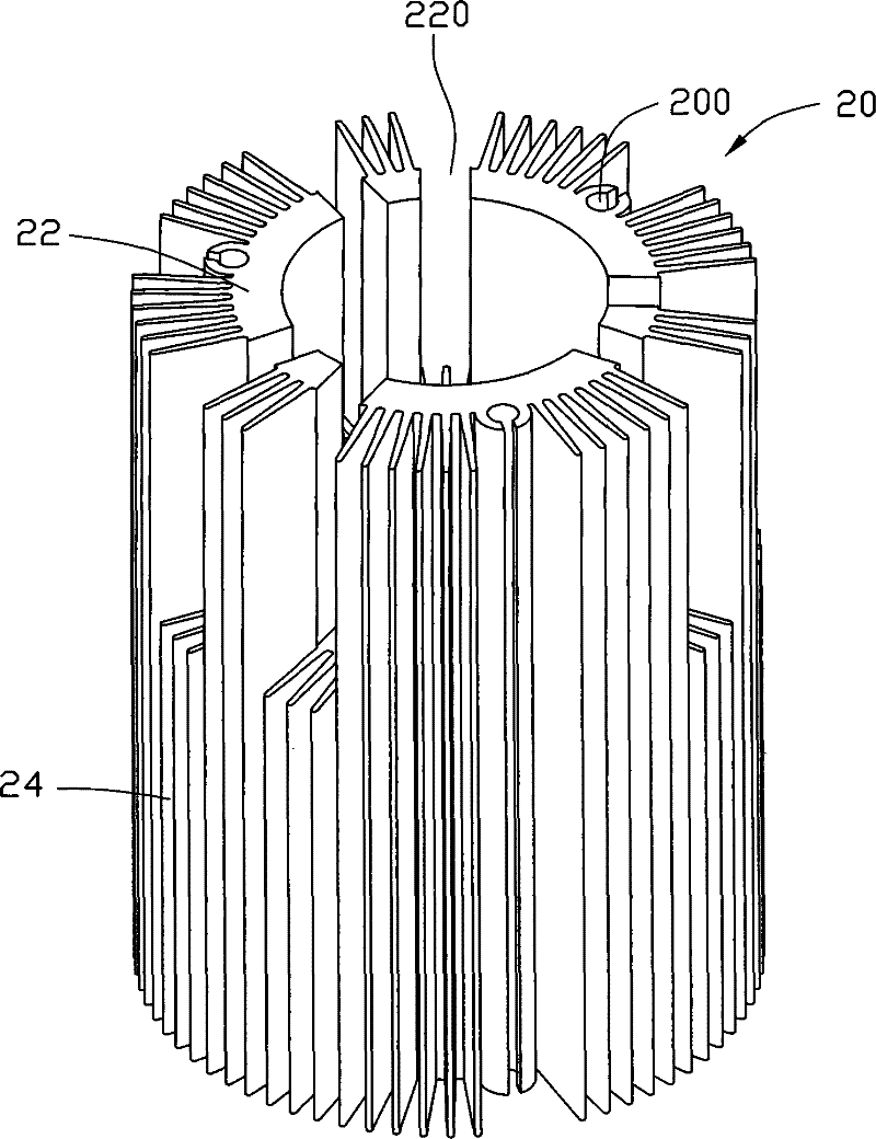
[0014] The light-emitting diode lighting device of the present invention is used to provide omnidirectional and large-area lighting for some specific occasions indoors and outdoors. Such as figure 1 and figure 2 As shown, the light-emitting diode lighting device of the present invention includes a lamp holder 10, a first radiator 20 connected to the lamp holder 10, three second radiators 30 arranged around the first radiator 20, respectively connected to the first , the three sets of heat pipes 40 of the second heat sink 20 and 30 and the light emitting diode assembly 50 attached to the outside of the second heat sink 30 . In addition, the top of the first heat sink 20 is also provided with a hat top 60 for decoration.

[0015] The lamp holder 10 includes a cylindrical body 12, the upper end of the body 12 is evenly provided with three bowl-shaped mounting parts 14 along the periphery of its outer wall, and a mounting hole 140 is opened in the center of each mounting part 1...


PUM


Abstract

An LED illumination device comprises a lamp holder, a first radiator arranged on the lamp holder, a plurality of LED combinations, a plurality of second radiators arranged on the periphery of the first radiator, and a plurality of heat tubes connected with the first radiator and the second radiators, wherein the heat tubes comprises a heat absorb section and a heat release section, the heat absorb section is arranged in the second radiator, the heat release section is arranged in the first radiator, and the LED combinations are attached to the second radiators. The first radiator is additionally arranged on the LED illumination device to assist in dissipating heat, and the LED illumination device gains higher radiating efficiency and simultaneously can control the volume of the radiators; moreover, the LED combinations are attached to the second radiators which are arranged on the periphery of the first radiator, so rays can be radiated to the periphery of the illumination device, and the better illuminating effect can be realized.

Description

technical field [0001] The invention relates to an illuminating device, in particular to an LED illuminating device with a cooling device. Background technique [0002] As an efficient light source, light-emitting diodes have been increasingly used in various fields. However, a large amount of heat is generated when the light-emitting diodes are working. If the heat is not dissipated in time, the light-emitting diodes may be overheated, resulting in a decrease in luminous efficiency. [0003] A traditional LED lighting device includes a plate-shaped radiator and several LEDs mounted on one side of the radiator. These light emitting diodes are evenly arranged on several straight lines. When the light-emitting diode is turned on, the heat generated by it is dissipated into the surrounding air through the radiator. [0004] However, since these light-emitting diodes are located on the same side of the heat sink, the light emitted by them can only radiate outward from this si...

Claims


Application Information

Patent Timeline
Patent Type & Authority Patents(China)
IPC IPC(8): F21V29/00H01L23/367H01L23/427F21Y101/02F21V29/51F21V29/76F21V29/77F21Y105/16F21Y115/10
Inventor 龙彬余光
Owner CHAMP TECH OPTICAL FOSHAN
Learn More