Light-emitting diode lamp

A technology of light-emitting diodes and lamps, which is applied to semiconductor devices of light-emitting elements, light sources, lampshades, etc., and can solve the problems of limited irradiation area, satisfaction, and difficulty for users.

Inactive Publication Date: 2010-06-09
CHAMP TECH OPTICAL FOSHAN +1
View PDF0 Cites 1 Cited by
  • Summary
  • Abstract
  • Description
  • Claims
  • Application Information

AI Technical Summary

Problems solved by technology

However, the light-emitting diode modules of lamps are generally placed horizontally on one side of the radiator to form a planar light source. This type of planar light source not only generates relatively concentrated heat, but also has a single irradiation direction and a limited irradiation area, so it cannot be placed around the lamp. Creates an even and soft lighting, which in many cases is difficult to please the user

Method used


Image

  • Light-emitting diode lamp
  • Light-emitting diode lamp
  • Light-emitting diode lamp

Examples


Embodiment Construction

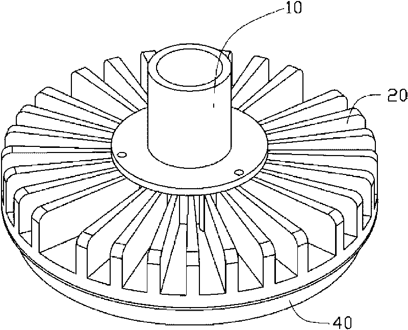
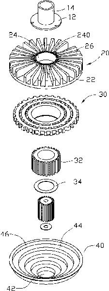
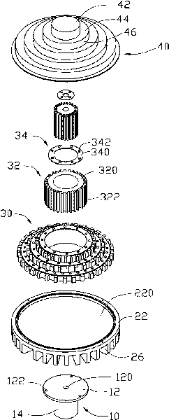
[0012] like Figure 1 to Figure 4 As shown, the light-emitting diode lamp of the present invention includes a positioning column 10, a first radiator 20 matched with the positioning column 10, a second radiator 30 attached and fixed on the bottom of the first radiator 20, and a second radiator 30 attached to the second radiator. A plurality of LED modules 34 of the heat sink 30 and a lampshade 40 covering the second heat sink 30 and cooperating with the first heat sink 20 are fixed. The positioning column 10 is used to fix the LED lamp at a desired position, such as the top of a house.

[0013] see figure 2 and image 3 , the positioning column 10 includes a circular base plate 12 and a hollow sleeve 14 extending vertically upward from the center of the base plate 12 . A through hole 120 is defined in the center of the base plate 12 , and three fixing holes 122 are evenly and spaced on the outer periphery of the base plate 12 , so that a fixing member (not shown) passes th...


PUM


Abstract

A light-emitting diode (LED) lamp comprises a first radiator, a second radiator fixed at the bottom of the first radiator, a plurality of LED modules attached to the second radiator and a lampshade which covers the second radiator and is fixed with the first radiator in a coordinated manner. The second radiator is provided with a plurality of heat conduction end faces which are hierarchically distributed and are different in sizes. The LED modules are correspondingly attached to the heat conduction end faces. The lampshade comprises a plurality of steps provided with concave lens structures and the steps are arranged corresponding to the LED modules. The light sent by the LED modules irradiates outwards after passing through the steps of the lampshade so as to obtain a larger lighting area. The steps of the lampshade are provided with concave lens structures, so that the light which is sent by the LED modules and has fixed direction is diverged after passing through the steps so as to obtain a larger lighting area.

Description

technical field [0001] The invention relates to a light-emitting diode lamp, in particular to a light-emitting diode lamp providing a larger lighting area. Background technique [0002] As an emerging third-generation light source, although it cannot replace traditional incandescent lamps on a large scale, it has the advantages of long working life, energy saving, and environmental protection, and is generally favored by the market. Moreover, the current modules composed of light-emitting diodes can produce high-power, high-brightness light sources, so they will widely and revolutionaryly replace existing light sources such as traditional incandescent lamps, and then become the main light source that meets the theme of energy conservation and environmental protection. [0003] As the power and brightness of LEDs or their modules increase, the heat generated by them will also increase. If the heating problem of LEDs cannot be properly resolved, the working life of LED lamps w...

Claims


Application Information

Patent Timeline
Patent Type & Authority Applications(China)
IPC IPC(8): F21V29/00F21V5/04H01L23/367F21Y101/02
CPCH01L2924/0002F21V21/116F21Y2101/02F21V5/04F21V29/2231F21V29/262F21K9/00F21V29/004F21V29/713F21V29/773F21V29/89F21Y2115/10F21K9/20F21K9/69F21V3/062F21V3/061H01L2924/00F21V29/777
Inventor 杨日朗余光
Owner CHAMP TECH OPTICAL FOSHAN
Why Eureka
Try Eureka