Lighting device of machine tool

A technology for lighting devices and machine tools, which is applied to lighting devices, lighting devices, components of lighting devices, etc., can solve the problems of inconvenient movement of lighting bulbs, cumbersome production and installation, and large space occupation, so as to eliminate lighting blind spots, save space, The effect of simplifying the structure

Inactive Publication Date: 2015-11-11
CHANGSHU JIANHUA MOLD TECH
View PDF9 Cites 1 Cited by
  • Summary
  • Abstract
  • Description
  • Claims
  • Application Information

AI Technical Summary

Problems solved by technology

This patent application solution solves the problem that the light bulb is inconvenient to move, but there are still technical problems mentioned by the applicant above, and the patent application solution also has the disadvantages of complex structure, large space occupation, and cumbersome production and installation.

Method used


Image

  • Lighting device of machine tool

Examples


Embodiment Construction

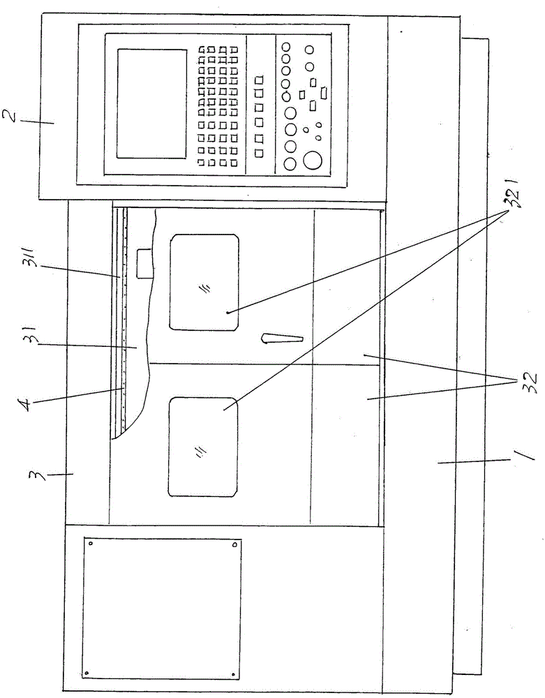
[0016] See figure 1 , provides the bed 1 of the structural system of the machine tool belonging to the known technical category, the bedside box 2 and the workpiece processing box box 3 arranged on the bedside 1, the bedside box 2 is located on the right side of the workpiece processing box box body 3 On the workpiece processing box body 3, a shield door 32 for shielding the working chamber 31 of the workpiece processing box body 3 is arranged. A light strip 4 of the structural system of the lighting device is given, and the light strip 4 is arranged along the top of the working chamber 31 in the length direction.

[0017] Depend on figure 1 As shown, there is a ceiling 311 (also called a ceiling) on ​​the top of the aforementioned working chamber 31, and the light strip 4 is fixed to the ceiling 311 along the length direction of the ceiling 311, specifically, the light strip 4 is fixed to the ceiling 311 through the light strip fixing piece. 4 is fixed on the ceiling 311. ...


PUM


Abstract

The invention belongs to the technical field of auxiliary equipment of a machine tool, and relates to a lighting device of a machine tool. The machine tool comprises a machine tool body, a machine tool head box arranged on the machine tool body and a workpiece machining box body. The machine tool head box is arranged on the right side of the workpiece machining box body. Shielding doors shielding a work cavity of the workpiece machining box body are assembled on the workpiece machining box body. A lighting device is a lamp band. The lamp band is arranged on the top in the length direction of the work cavity. Due to the fact that the lamp band is adopted and arranged on the top in the length direction of the work cavity, the lighting area can be obviously expanded, the lighting dead angle is eliminated, and an operator can conveniently clamp a workpiece and observe the machining situation of the workpiece in the work cavity outside the shielding doors. Due to the fact that the lamp band is adopted, the structure can be greatly simplified, space is saved, and installation is convenient; and due to the fact that the LED lamp band has the superior brightness and is low in power consumption, the electric energy consumption can be reduced easily.

Description

technical field [0001] The invention belongs to the technical field of auxiliary equipment for machine tools, and in particular relates to a lighting device for machine tools. Background technique [0002] The machine tool mentioned above refers to a closed machine tool. The so-called closed machine tool means that only a sliding door or a rotary opening door is provided on the side facing the operator, while the rest of the machine is in a closed state. [0003] As is known in the industry, a light bulb is usually arranged in the aforementioned machine tool so that the operator can easily clamp the workpiece and check the processing of the workpiece by the machine tool through a transparent door. However, in the actual use process, because the interior is relatively dark, it is difficult for the operator to see the processing situation clearly with only one light bulb. Especially in the process of drilling and cutting the workpiece by the machine tool, the light bulb is ea...

Claims


Application Information

Patent Timeline
Patent Type & Authority Applications(China)
IPC IPC(8): B23Q11/00F21S4/00F21V33/00F21W131/403
CPCB23Q11/00F21V33/00F21W2131/403
Inventor 晏庆宝马军英方朝辉苏谦陈俊朱宇庭
Owner CHANGSHU JIANHUA MOLD TECH
Why Eureka
Try Eureka