Eureka AIR delivers breakthrough ideas for toughest innovation challenges, trusted by R&D personnel around the world.

Double-shaft and double-brush rolling cleaning device of back rolling type sweeping car

A technology of cleaning device and road sweeper is applied in road cleaning, cleaning methods, construction and other directions, which can solve the problems of reducing the volume of garbage bins, increasing the quality of vehicle equipment, and increasing fuel consumption.

Active Publication Date: 2009-09-30
扫地王(天津)专用车辆装备有限公司
View PDF0 Cites 8 Cited by
  • Summary
  • Abstract
  • Description
  • Claims
  • Application Information

AI Technical Summary

Problems solved by technology

[0002] At present, most of the locomotives for cleaning garbage on the domestic market are suction-sweeping vehicles, that is, road sweepers need two sets of engines, one is the main engine for driving and cleaning, and the other is equipped with auxiliary engines and fans. The disadvantage of the road sweeper is that it not only increases the fuel consumption, but also greatly reduces the volume of the garbage bin and increases the equipment quality of the vehicle due to the addition of an auxiliary engine and a fan on the vehicle equipment.

Method used


Image

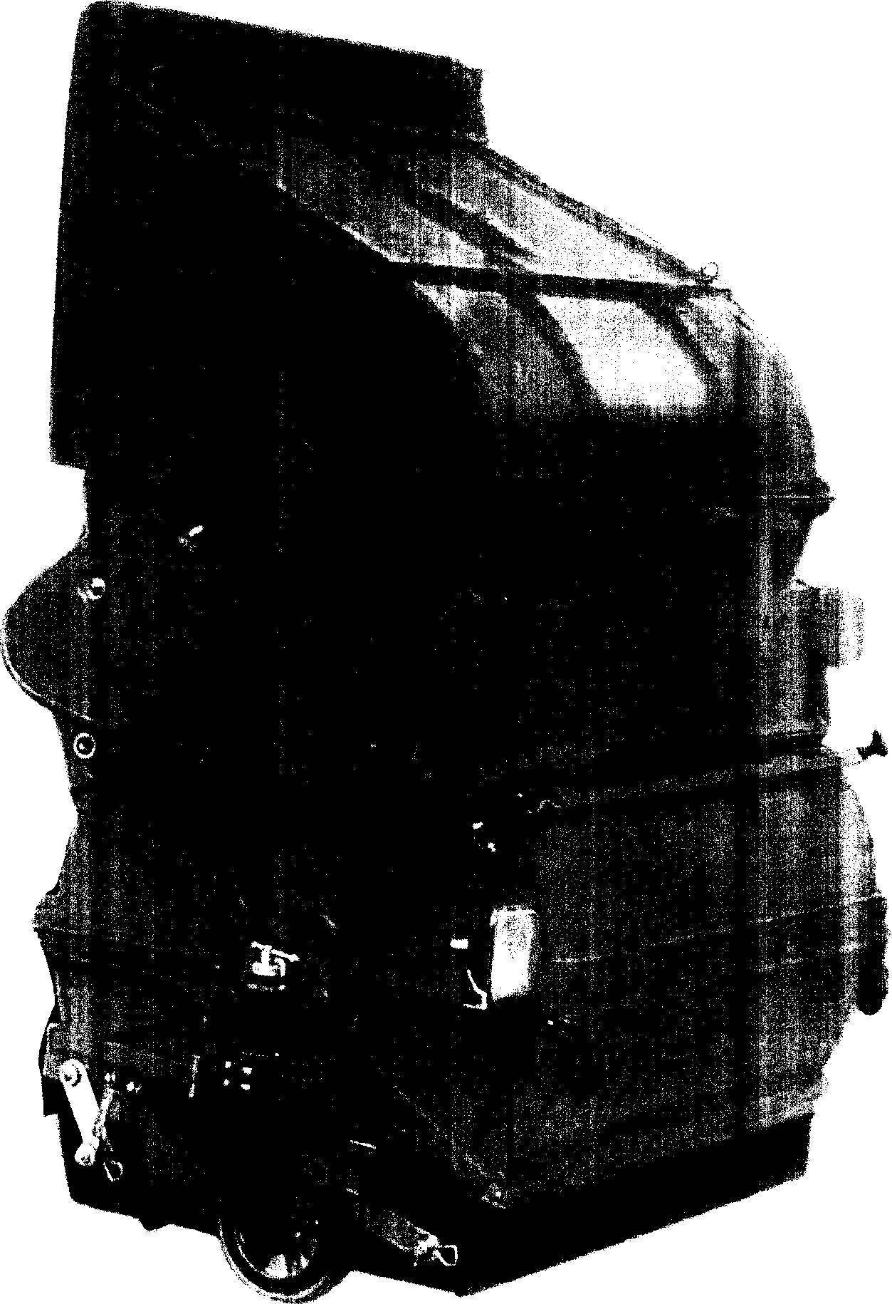
  • Double-shaft and double-brush rolling cleaning device of back rolling type sweeping car
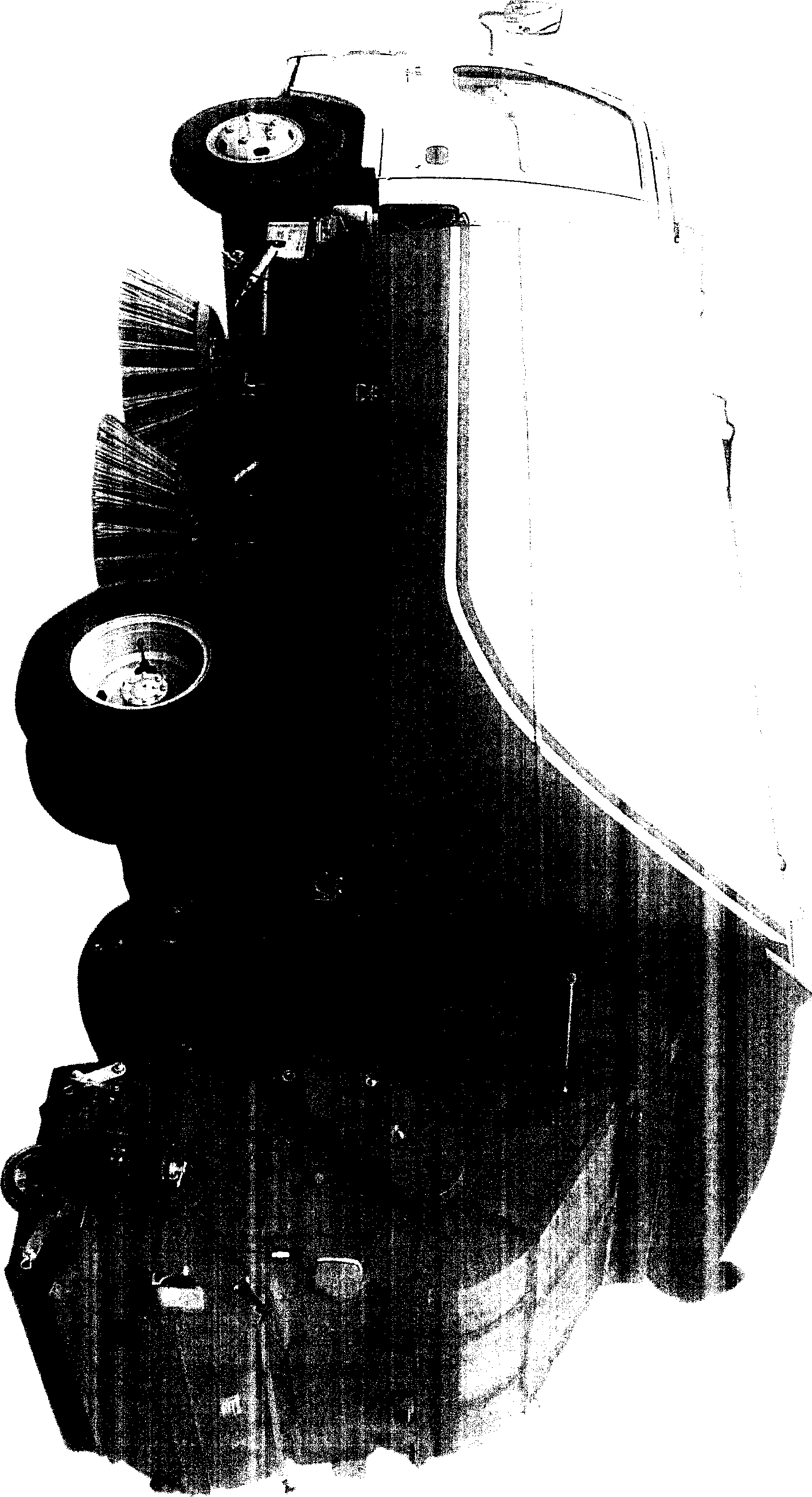
  • Double-shaft and double-brush rolling cleaning device of back rolling type sweeping car
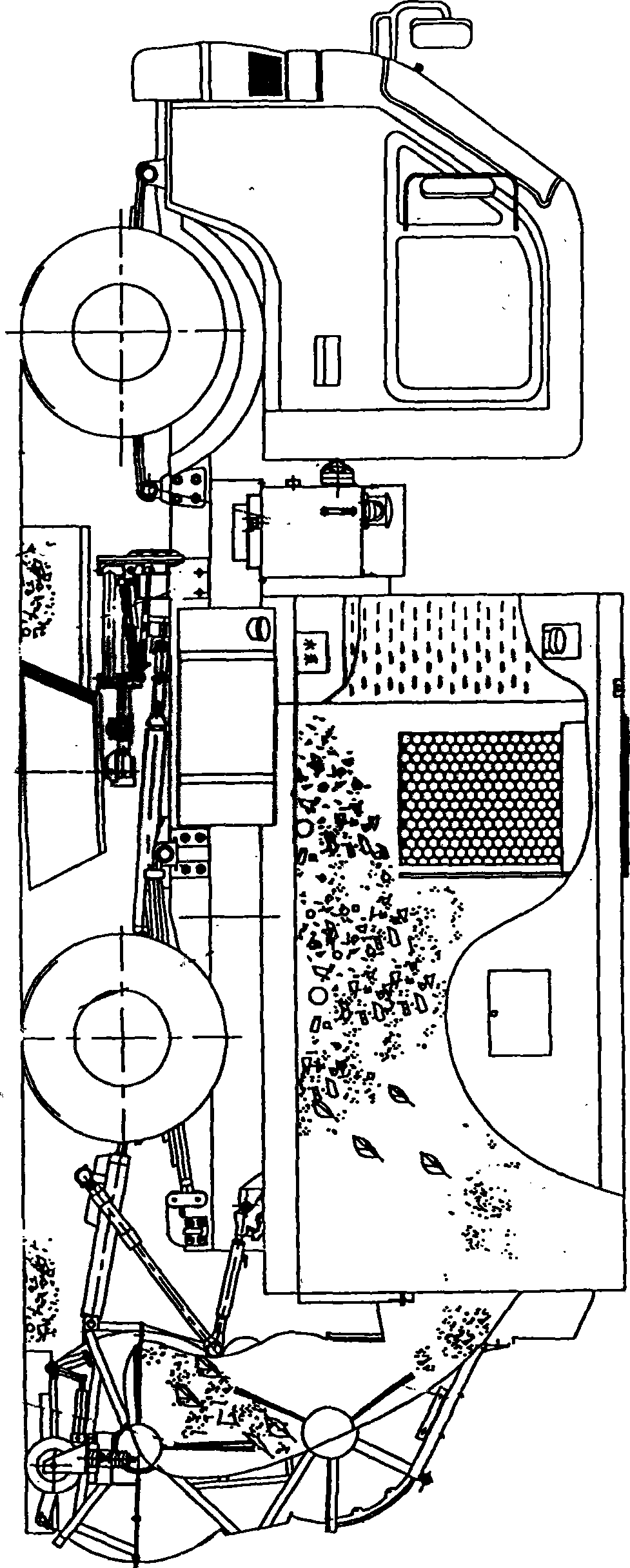
  • Double-shaft and double-brush rolling cleaning device of back rolling type sweeping car

Examples


Embodiment Construction

[0020] exist Figure 4 , Figure 5 , Image 6 , Figure 7 , in the shown embodiment, the hydraulic motor (18) is connected to the hydraulic pump and the electric-hydraulic control valve on the road sweeper through the hydraulic oil pipe. When the road sweeper engine provides power, the hydraulic motor (18) starts to work, The hydraulic motor (18) drives the driving wheel in the gearbox (19) through the output shaft, and the driving wheel drives the driven wheel (22) to rotate, and the driven wheel (22) drives the upper brush main transmission shaft (17) through the output shaft, and the upper The brush driving shaft (17) is connected with the left sprocket wheel (15), and then the chain (16) drives the upper roller brush main transmission shaft sprocket wheel (3) to rotate, and the upper roller brush rotating shaft (31) is driven by the chain wheel (3) to rotate, The rotating shaft (31) drives the upper roller brush (29) connected with it to rotate through the upper roller ...


PUM


Abstract

The invention relates to a double-shaft and double-brush rolling cleaning device of a back rolling type sweeping car, which mainly comprises an upper box, a middle box, a lower box, a hydraulic motor, a gear box, an upper brush main transmission shaft, a lower brush main transmission shaft, a left sprocket wheel, a right sprocket wheel, an upper rolling brush rotating shaft of a chain, a lower rolling brush rotating shaft of the chain, an upper rolling brush, a lower rolling brush, and the like, wherein the hydraulic motor respectively drives a driven wheel and an output shaft through the gear box and a driving wheel inside the gear box to respectively drive the upper brush main transmission shaft and the lower brush main transmission shaft, drives the upper rolling brush rotating shaft and the lower rolling brush rotating shaft through sprocket wheel chains of the upper brush main transmission shaft and the lower brush main transmission shaft and also drives the rolling brushes connected with shafts through the upper rolling brush rotating shaft and the lower rolling brush rotating shaft; when the lower rolling brush rotates, trashes swept by two lateral brushes arranged at the lower side of the back rolling type sweeping car are swept to the middle of a rear rolling box in a rolling way, and the upper rolling brush continuously sweeps the trashes to a trash collecting box in a rolling way. The circumference of the lower edge of the rear rolling box is provided with a front baffle, a rear baffle, a left baffle and a right baffle, thereby the invention can prevent dust from flying.

Description

1. Technical field: [0001] The invention relates to a cleaning device on sanitation equipment, in particular to a double-axis double-brush rolling cleaning device of a rear-rolling road sweeper. 2. Background technology: [0002] At present, most of the locomotives for cleaning garbage on the domestic market are suction-sweeping vehicles, that is, road sweepers need two sets of engines, one is the main engine for driving and cleaning, and the other is equipped with auxiliary engines and fans. The disadvantage of the road sweeper is that it not only increases the fuel consumption, but also greatly reduces the volume of the garbage bin and increases the equipment quality of the vehicle due to the addition of an auxiliary engine and a fan on the vehicle equipment. [0003] And adopt the dual-axle double-brush rolling cleaning device of the rear roller type road sweeper of the present invention to remove the equipment of auxiliary engine and blower fan on the overall equipment o...

Claims


Application Information

Patent Timeline
IPC IPC(8): E01H1/04E01H1/05
Inventor 刘云成
Owner 扫地王(天津)专用车辆装备有限公司
Why Eureka
Eureka Blog
Learn More