Vehicle upper body structure

A body and vehicle technology, applied in the directions of superstructure, superstructure sub-assemblies, vehicle components, etc., can solve the problems of reducing the strength of the vehicle roof structure 201, not completely satisfactory, etc.

Inactive Publication Date: 2009-09-30
HONDA MOTOR CO LTD
View PDF2 Cites 26 Cited by
  • Summary
  • Abstract
  • Description
  • Claims
  • Application Information

AI Technical Summary

Problems solved by technology

[0004] The previously constructed vehicle roof structure 201 is not entirely satisfac...

Method used


Image

  • Vehicle upper body structure
  • Vehicle upper body structure
  • Vehicle upper body structure

Examples


Embodiment Construction

[0030] Some preferred embodiments of the present invention will be described in more detail below with reference to the accompanying drawings.

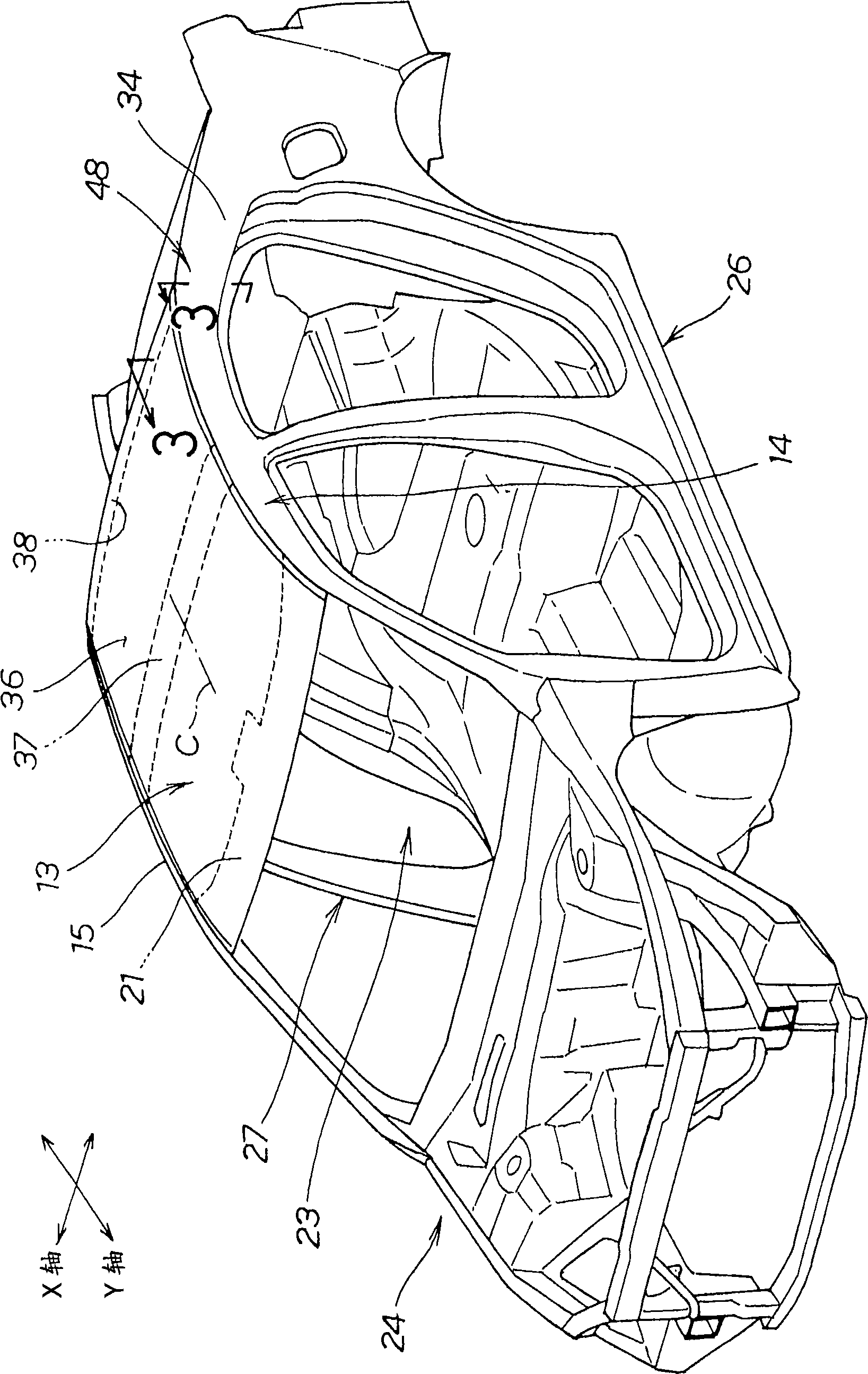
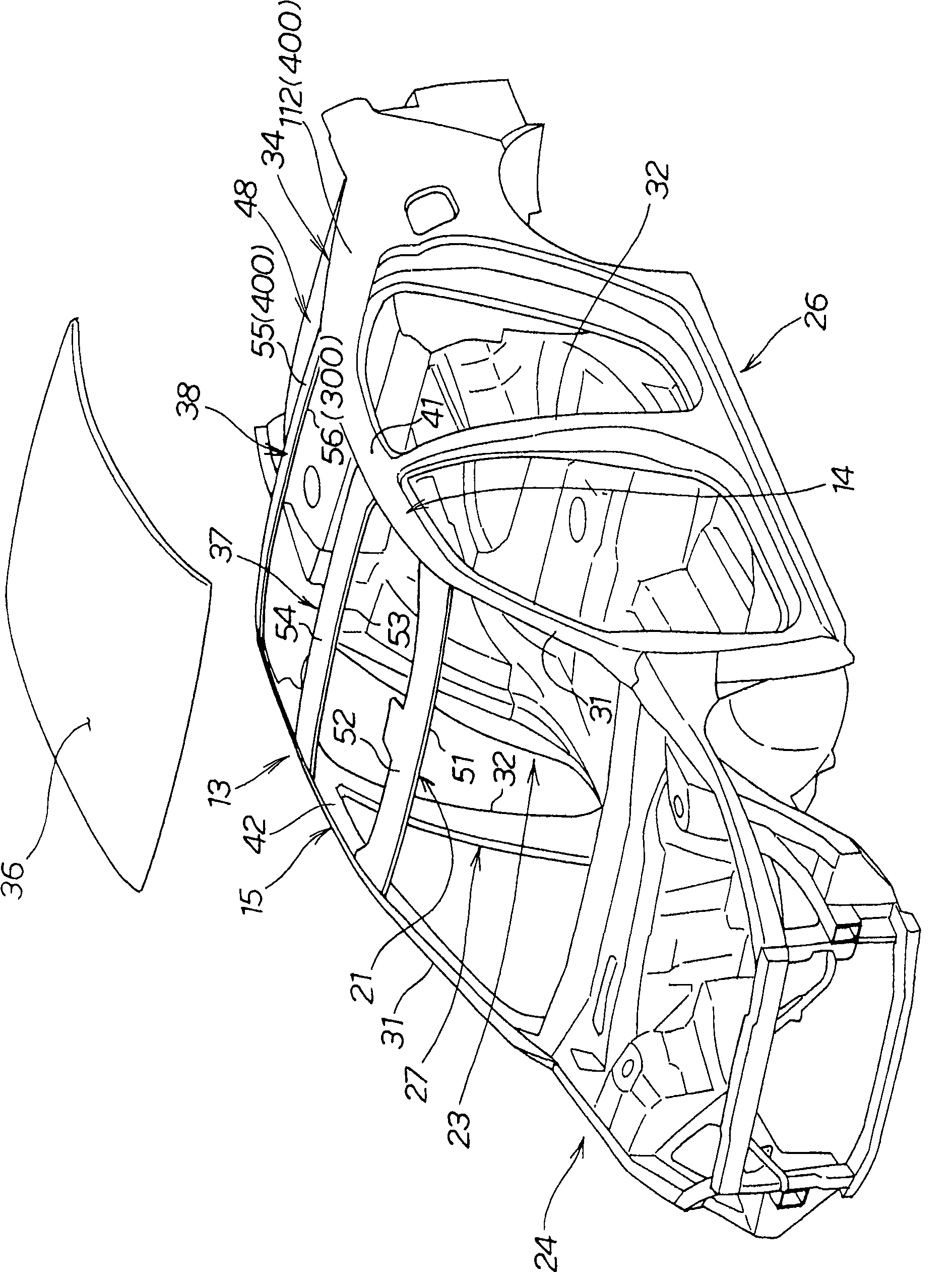
[0031] figure 1 and figure 2 A perspective view of a body in white (BIW) comprising an upper body structure according to a first embodiment of the invention is shown. like figure 1 Body 24 is shown having a passenger compartment 23 , a left side body structure 26 forming a left wall of passenger compartment 23 , a right side body structure 27 forming a right wall of passenger compartment 23 , and a roof 13 forming a top wall of passenger compartment 23 . The left body structure 26 and the right body structure 27 are symmetrical to each other with respect to the longitudinal central axis C (Y axis) of the body 24 , and therefore, the left body structure 26 will be mainly described.

[0032] like figure 2 As shown, the left side body structure 26 includes a front pillar 31 , a center pillar 32 and a rear pillar 34 connected at t...


PUM


Abstract

A vehicle upper body structure includes an inner member (300) and an outer member (400) assembled together to form a roof side rail (14), a pillar (34) and a roof cross rail (38) joined together at a junction (48). The junction includes an inverted U-shaped reinforcement bracket (118) having two legs (125, 126) joined to the inner member and a central web (127) extending between the legs, and a reinforcement panel (115) disposed between the inner and outer members and retained on an upper surface of the central web of the reinforcement bracket. The outer member is joined to an upper surface of the reinforcement panel.

Description

technical field [0001] The present invention relates to a vehicle upper body structure suitable for use on the upper part of the body including the roof. Background technique [0002] The roof of a vehicle generally includes a frame and a roof panel formed of sheet metal and connected to the frame. One example of a known vehicle roof structure is shown in Japanese Laid-Open Patent (JP-A) No. 2005-153649. [0003] as here Figure 13 As shown, the disclosed vehicle roof structure includes a roof side rail 202 , a roof center rail 203 and a roof panel 205 connected by spot welding. The roof side beams 202 and the roof center beams 203 have closed cross-sectional structures to improve the rigidity of the vehicle body against lateral or transverse impacts. The roof center rail 203 of closed cross-sectional structure has a first access hole 204 to allow a welding electrode (not shown) to reach the welding point when welding the roof center rail 203 and the roof side rails 202 to...

Claims


Application Information

Patent Timeline
IPC IPC(8): B62D27/02B62D25/06
CPCB62D25/06B62D25/07
Inventor 保坂宣夫前岛一骑
Owner HONDA MOTOR CO LTD
Why Eureka
Try Eureka