Biomass reactor

A technology for reactors and biomass materials, applied in the field of reactors, can solve the problems of lack of benefits and high costs

Inactive Publication Date: 2009-09-30
布里安·安东尼·埃文斯
View PDF0 Cites 1 Cited by
  • Summary
  • Abstract
  • Description
  • Claims
  • Application Information

AI Technical Summary

Problems solved by technology

Such materials are often landfilled or burned for little benefit and often at high cost

Method used


Image

  • Biomass reactor
  • Biomass reactor
  • Biomass reactor

Examples


Embodiment Construction

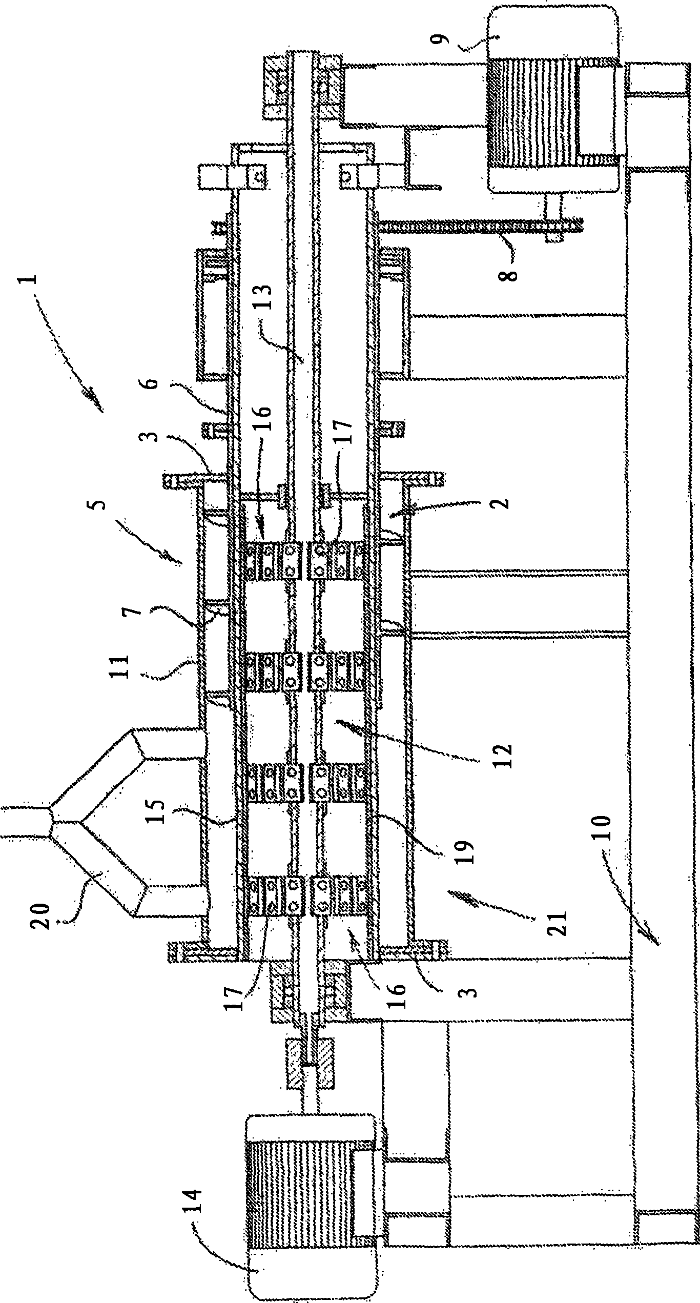
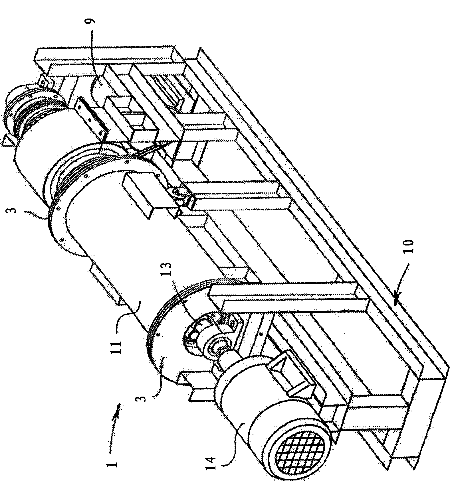
[0016] Referring to the accompanying drawings, the biomass reactor (1 ) comprises a feed screw conveyor (2) located at one end of an annular chamber (4) and extending into the annular chamber. The inlet (5) adjacent this end of the chamber (4) will feed the screw conveyor (2).

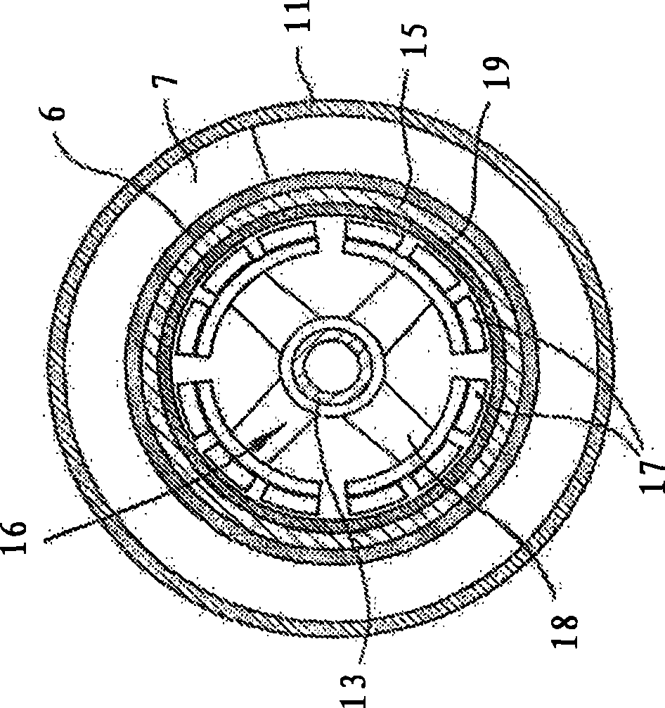
[0017] The conveyor (2) comprises a cylinder (6) with an outwardly protruding helix (7). The cylinder (6) is connected to the first electric motor (9) by a chain (8), which is driven by the first electric motor (9). The first electric motor (9) may be variable speed.

[0018] The reactor (1) is mounted on a suitable frame (10). The chamber (4) comprises a housing (11) containing biomass material.

[0019] A reactor heating device (12) is arranged in the core of the annular chamber (4). Supported at a distance from the machine base (10) and outside the chamber (4) is a shaft (13) mounted in bearings. The shaft (13) is connected to and driven by the second electric motor (14). The shaft (13) extend...


PUM


Abstract

The invention provides a reactor for the conversion of biomass material. The reactor has an elongate annular chamber with an inner wall and outer casing. A heat source is located within the inner wall of the chamber. A screw conveyor extends from one end into the chamber to feed biomass material. At the other end is an outlet. The heat source is provided as a series of permanent magnet assemblies mounted for rotation within a sleeve of electrically conductive material. The sleeve is provided by the inner wall of the chamber which is made from suitable stainless steel. Each magnet assembly has a series of magnets spaced apart on the periphery of a circular support. A layer of insulating material is located between the magnet assemblies and the sleeve. A rotatable shaft adapted for connection to a driving power source provides a mounting for the magnet assemblies. The reactor is preferably fitted with a heat exchanger through which a suitable fluid, heat transfer medium is circulated. An onboard computer monitors temperatures in the reaction chamber and magnet chamber and automatically controls operation of the reactor with the information it receives. The invention extends to the heat source of the kind described for a biomass reactor.

Description

technical field [0001] The present invention relates to a reactor for converting biodegradable materials by heating. The invention extends to means for generating heat in and from such reactors. Background technique [0002] A large amount of biodegradable waste materials are generated from different sources, which often need to be disposed of. Such materials are often landfilled or burned for little benefit and often at high cost. [0003] Especially in rural areas where "clean energy" cannot be used in the form of electricity, the environment is often destroyed by sewage, garbage and excess vegetation. Contents of the invention [0004] The object of the present invention is to provide a device with which biomass of the type described can be converted into useful materials, in particular energy from which energy can be obtained and used in the form of electrical energy. [0005] According to the present invention there is provided a reactor for converting biomass mate...

Claims


Application Information

Patent Timeline
Patent Type & Authority Applications(China)
IPC IPC(8): C02F11/10C02F1/48C10B47/44C10B53/02
CPCC02F11/10C02F1/481C10B47/44Y02E50/14C10B19/00C10B53/02Y02W10/40Y02P20/145Y02E50/10
Inventor 布里安·安东尼·埃文斯
Owner 布里安·安东尼·埃文斯
Why Eureka
Try Eureka