Plate bending machine capable of automatically adjusting multiunit upper supporting roller device

An automatic adjustment and rolling machine technology, which is applied in the field of forging machinery, can solve the problems of not being able to fully adhere to the bottom plane of the girder, difficulty in balancing, and inconvenient operation, etc., to shorten the preparation time of the rolling plate, improve the precision, and improve the rolling operation. convenient effect

Inactive Publication Date: 2009-10-07
南通恒力重工机械有限公司
View PDF0 Cites 6 Cited by
  • Summary
  • Abstract
  • Description
  • Claims
  • Application Information

AI Technical Summary

Problems solved by technology

This kind of device is a separate vertical adjustment of the upper idler device. There are electric push-pull rods and the longitudinal structural size of the motor, which affect the structural size of the upper idler. They can only be adjusted separately. The work efficiency is low and the operation is inconvenient.
The above-mentioned pressing parts only have a single set of anti-pressure devices such as pull rods, springs, and pressure plates. For example, the upper idler device is lengthened and widened, which is difficult to balance and cannot be completely attached to the bottom plane of the girder.

Method used


Image

  • Plate bending machine capable of automatically adjusting multiunit upper supporting roller device
  • Plate bending machine capable of automatically adjusting multiunit upper supporting roller device

Examples


Embodiment Construction

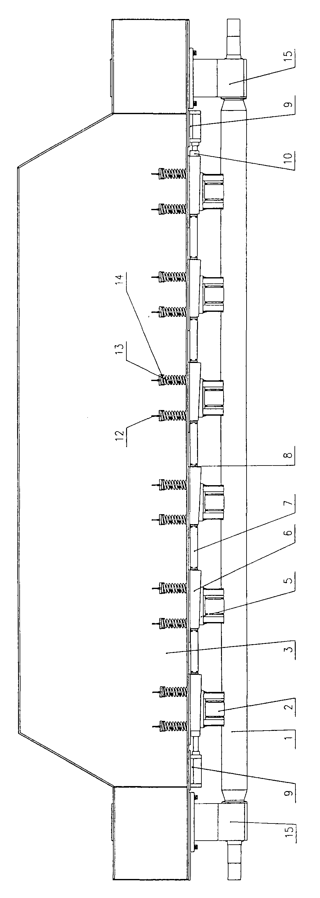
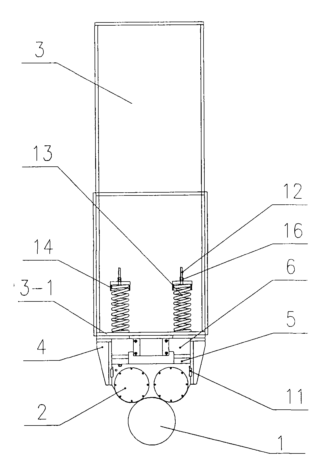
[0012] Such as figure 1 , 2 As shown, the girder 3 is provided with a bottom plate 3 - 1 , and the upper roller 1 is supported by two sets of bearings 15 at both ends under the girder 3 . Multiple sets of upper roller devices 2 are arranged between the upper roller 1 and the girder 3 .

[0013] The lower ends of the two ends of the girder 3 are fixedly connected to the oil cylinders 9 respectively. The telescopic rods of the two groups of oil cylinders 9 are coaxially opposite and parallel to the upper roller 1. Between the two telescopic rods of the two groups of oil cylinders 9, the connecting beam 7 is connected by a connecting block 10. , fixedly connect seven vertically inclined irons 6 along the length direction of the connecting beam 7 on the connecting beam 7 .

[0014] Positioning seats 4 are respectively fixed on the front and rear sides of the lower end of the girder 3 , and vertical key grooves are respectively arranged on the two inner sides opposite to the posi...


PUM


Abstract

The invention relates to a plate bending machine capable of automatically adjusting multiple groups of upper supporting roller devices, which belongs to the technical field of structures of super wide plate bending machines. Each group of upper supporting roller device is hung on the lower end of a beam through a spring, and the upper ends of the upper supporting roller devices are fixedly connected with fixed longitudinal lower inclined irons; the lower ends of both heads of the beam are respectively fixedly connected with oil tanks, telescopic links of the two oil tanks are coaxially opposite and parallel to upper rollers, a connection beam is connected between the two telescopic links of the two oil tanks, longitudinal upper inclined irons are uniformly distributed on the connection beam, and the lower surface of each longitudinal upper inclined iron is respectively contacted with the upper end surfaces of the corresponding fixed longitudinal lower inclined irons; the front side and the rear side of the lower end of the beam are respectively fixed with positioning seats, two inner lateral surfaces opposite to the positioning seats are respectively provided with vertical key slots, and the front side and the rear side of each group of upper supporting roller device are connected with the positioning seats through guide keys inside the key slots. The invention can fast synchronously adjust the multiple groups of upper supporting roller devices, reduce the time of plate bending preparatory processes, enable the plate bending operation to be more convenient and enhance the precision of plate bending products.

Description

technical field [0001] The invention relates to the technical field of forging machinery, especially the structure of an ultra-wide plate bending machine. Background technique [0002] In the existing plate rolling machine with multiple sets of upper roller devices, multiple sets of upper roller devices are arranged above the upper rollers, and each group of upper roller devices is respectively installed on the bottom surface of the girder above the upper roller device. When installing the upper roller device, pre-add different thicknesses to adjust the backing plate to increase the installation center height of the upper roller device, which is used to compensate the deflection of the plate rolling machine on the beam caused by the plate rolling, so as to ensure the accuracy of the plate rolling product. When rolling steel plates with different specifications, it is necessary to change the thickness of the backing plate installed on the upper supporting roller device again,...

Claims


Application Information

Patent Timeline
Patent Type & Authority Applications(China)
IPC IPC(8): B21D5/14
Inventor 夏日东吴桂林李斌于荣川刘兆荣李荣堂王兴仁
Owner 南通恒力重工机械有限公司
Why Eureka
Try Eureka