
Clutch mechanism

A clutch mechanism and clutch device technology, applied in clutches, mechanical drive clutches, mechanical equipment, etc., can solve problems such as injury to the patient or surgeon of the carrier, and increase the risk of misoperation of the carrier.

Inactive Publication Date: 2009-10-07
PROSURGICS
View PDF3 Cites 2 Cited by
  • Summary
  • Abstract
  • Description
  • Claims
  • Application Information

AI Technical Summary

Problems solved by technology

Then, when the components start to separate, the weight of the carrier may cause the load to be lost because the weight of the carrier and the instrument attached to it is suddenly no longer supported by the tool gripping mechanism and, for example, may be heavier than the user expects. involuntary movement
In addition, the movement of the carrier after component separation increases the risk of other misoperations of the carrier
In surgical applications, misoperation of the carrier can be a serious safety issue (potentially causing injury to the patient or surgeon)

Method used


Image

  • Clutch mechanism
  • Clutch mechanism
  • Clutch mechanism

Examples


Embodiment Construction

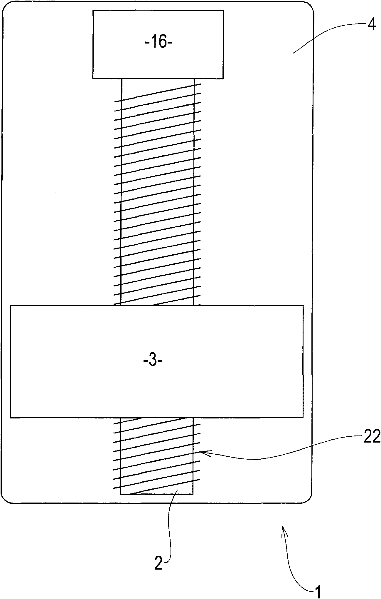
[0029] refer to figure 1 , an embodiment of the present application includes a linear drive device 1 .

[0030] The linear drive device 1 comprises a threaded shaft 2 and a motor 16 connected to the threaded shaft, activating the motor 16 causes the threaded shaft 2 to rotate. Preferably, the motor 16 is connected to the proximal end of the threaded shaft 2 . This connection can be achieved through the use of a gearbox (not shown) or through a direct connection.

[0031] The threaded shaft 2 and the motor 16 are installed in the housing 4 . The motor 16 is fixed to the housing 4 and is prevented from rotating relative to the housing. This can be achieved eg by using adhesive or one or more screws. Alternatively, motor 16 may have a base (not shown) integrally formed with housing 4 . Other installations are also possible.

[0032] The threaded shaft 2 is driven by a motor 16 to rotate freely relative to the housing 4 . In one embodiment, a bearing (not shown) is provided...


PUM


Abstract

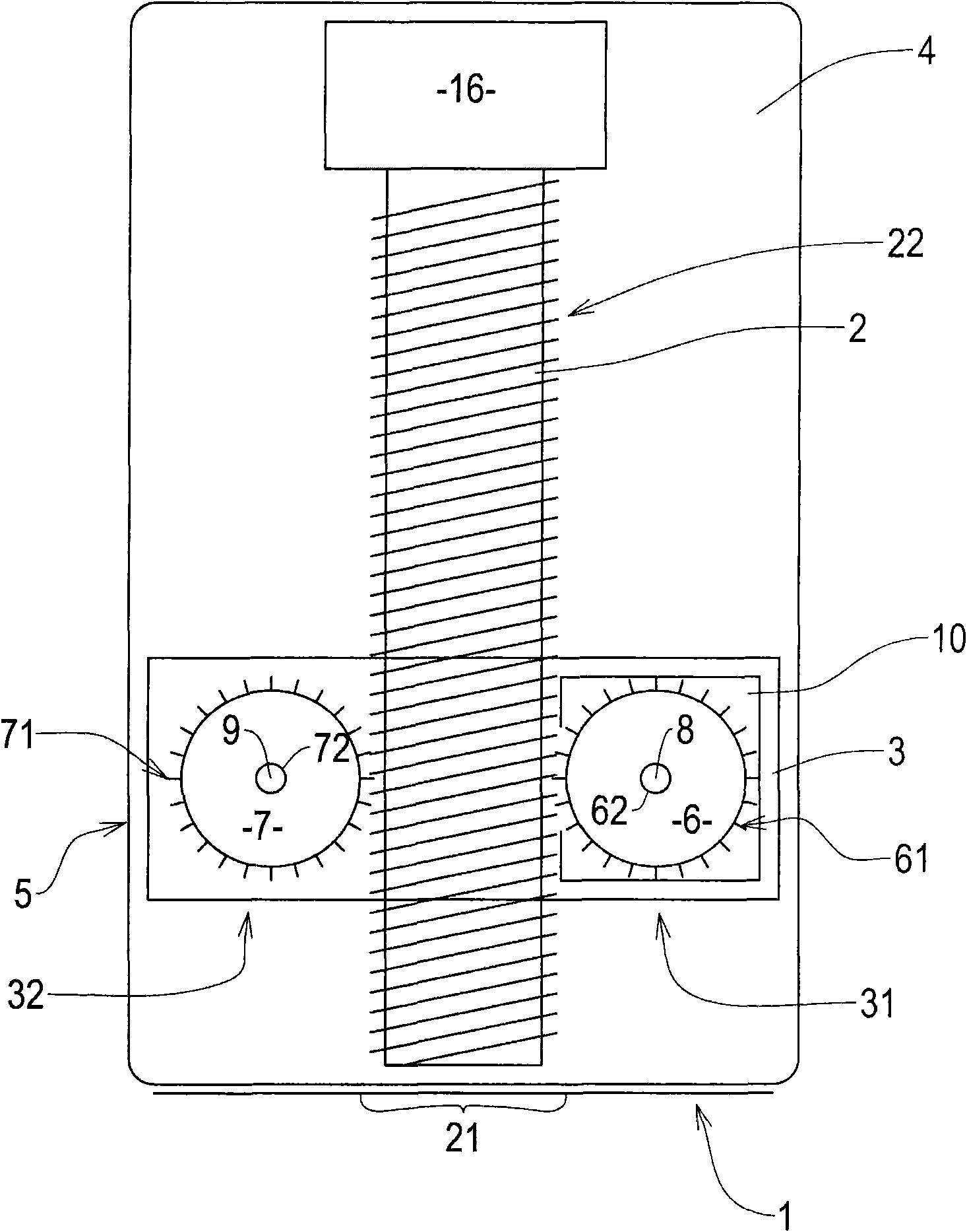
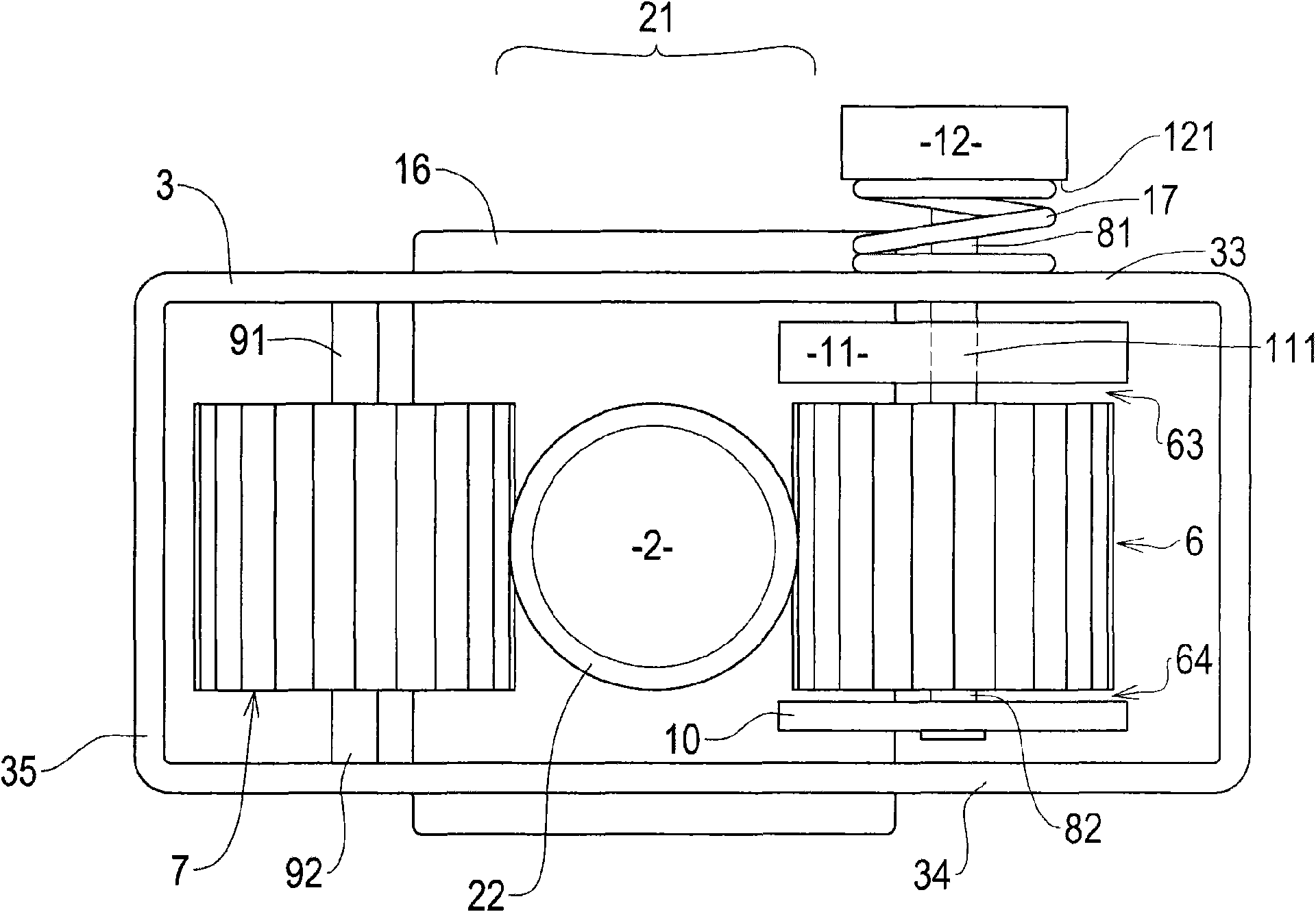
A clutch mechanism 5 for use with a carrier of a linear drive device 1, the mechanism 5 comprising: a housing 3; a first gear 6 coupled to the housing 3 and having gear teeth 61 configured to engage a threaded shaft 2 of a linear drive device 1, such that rotation of the shaft 2 causes the housing 3 to move along the shaft 2 in a first mode of operation; and a first clutch arrangement associated with the first gear 6 and configured to prevent substantial rotation of the first gear 6 with respect to the housing 3 when a rotational force applied to the first gear 6 is less than a threshold force and to permit rotation of the first gear 6 with respect to the housing 3 when a rotational force applied to the first gear 6 is greater than the threshold force, such that the housing 3 can be manually moved along a length of the shaft 2, in a second mode of operation, by exerting a force on the housing 2 such that the rotational force applied to the first gear 6 through the interaction of the threaded shaft 2 and the gear teeth exceeds the first threshold.

Description

technical field [0001] Embodiments of the present invention relate to clutch mechanisms for use with linear drives, to linear drives including such clutch mechanisms, and to surgical tool gripping mechanisms including such linear drives. In particular, embodiments of the present invention relate to a surgical tool gripping mechanism including a linear drive and a clutch mechanism. Background technique [0002] Various applications of linear drives are known. Typically, these devices include a motor connected to a threaded shaft and a carrier mounted on the threaded shaft. The carrier has an element threadedly engaged with the threaded shaft, and the carrier is prevented from rotating about the threaded shaft when the motor drives the threaded shaft to rotate, so that the carrier is driven in linear motion along the length of the threaded shaft. Reverse rotation of the threaded shaft reverses the direction of linear motion of the carrier along the threaded shaft. The motor...

Claims


Application Information

Patent Timeline
IPC IPC(8): F16D23/12A61B17/00
CPCF16H2025/2046F16H25/2021
Inventor 戴维·盖尔阿德里安·库珀基思·马歇尔
Owner PROSURGICS
Learn More