Automatic expansion compensation type pipe joint

A pipe joint and compensation type technology, which is applied in the expansion compensation device for pipelines, pipes/pipe joints/fittings, pipe components, etc., can solve problems such as leakage

Inactive Publication Date: 2009-10-07
陈阵
View PDF2 Cites 17 Cited by
  • Summary
  • Abstract
  • Description
  • Claims
  • Application Information

AI Technical Summary

Problems solved by technology

[0005] The task of the present invention is to provide a self-expanding compensating pipe joint that solves the problem of leakage caused by the deformation of the pipe joint due to thermal expansion and contraction by increasing the radial thickness of the elastic seal

Method used


Image

  • Automatic expansion compensation type pipe joint
  • Automatic expansion compensation type pipe joint
  • Automatic expansion compensation type pipe joint

Examples


Embodiment Construction

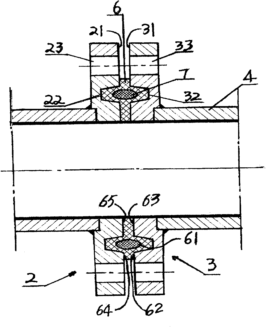
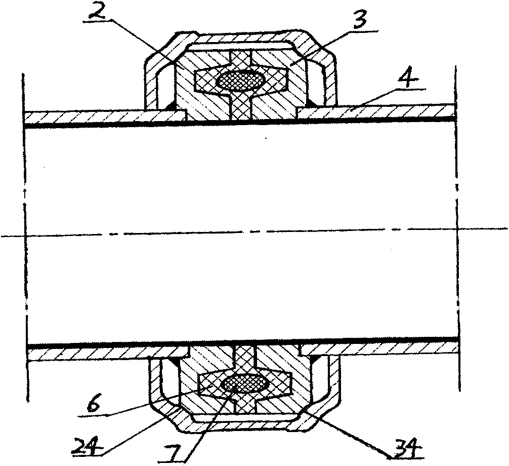
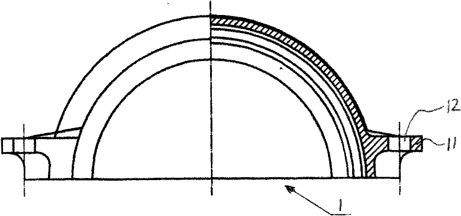
[0019] see figure 1 and Figure 5 , these two drawings show the overall structure of the appearance of the first embodiment of the self-expansion compensating pipe joint proposed by the present invention. The pipe joint includes a first joint part 2 and a second joint part 3 respectively arranged at the ends of two pre-connected pipes 4 , and an elastic sealing part 6 .

[0020] The first joint part 2 and the second joint part 3 can be made into a structure similar to that of flanges in the prior art, that is, they are made of disc-shaped plates, and axial through holes 23 and 33 are arranged on them. . Corresponding annular recesses 22 and 32 are respectively provided on the abutting end surfaces 21 and 31 of the first joint part 2 and the second joint part 3 . An elastic sealing member 6 is respectively installed in the annular recesses 22 and 32 , and each elastic sealing member 6 is provided with an annular groove 61 perpendicular to the annular recesses 22 and 32 and h...


PUM


Abstract

The invention relates to an automatic expansion compensation type pipe joint, comprising a first joint part and a second joint part which are respectively arranged at the end parts of two pre-connection pipes; the butt-joint end surfaces of the first joint part and the second joint part are respectively provided with a ring concave part which is concave inwards in the radial direction; and the position where each ring concave part is located is provided with an elastic sealing part which can extend into the ring concave part and a connecting part used for limiting the position of the first joint part and the second joint part. The ring concave part can lead the elastic sealing part to be capable of realizing automatic expansion type sealing in the state of bending state; and the pipelines connected by utilizing the pipe joint are not affected by the temperature of external environment basically.

Description

Technical field: [0001] The invention relates to a self-expansion compensating pipe joint. Background technique: [0002] The pipeline used to convey fluids is composed of many tubes connected axially by fittings. Traditional pipe joints usually use flanges installed at the ends of two pre-connected pipes respectively, and the two butt flanges are axially tightened and fixed by bolts. At the same time, in order to prevent the fluid in the pipeline from being There is leakage between the flanges, and a sealing ring made of rubber material is installed between the two butt flanges. Although the structure of the pipe joint of this kind of structure is relatively simple, for the long-distance transmission fluid pipeline on the ground, the pipeline will be directly affected by the external environment temperature and will expand with heat and contract with cold. , and during thermal expansion, the pipe joints will be deformed due to the increase in the length of the pipeline, w...

Claims


Application Information

Patent Timeline
Patent Type & Authority Applications(China)
IPC IPC(8): F16L51/00F16L23/16
Inventor 陈阵
Owner 陈阵
Why Eureka
Try Eureka