Led backlight module system

A light-emitting system and light source technology, applied in the fields of display image systems, electronic devices, and light-emitting systems, can solve problems affecting display quality, etc.

Inactive Publication Date: 2009-10-07
TPO DISPLAY
View PDF0 Cites 7 Cited by
  • Summary
  • Abstract
  • Description
  • Claims
  • Application Information

AI Technical Summary

Problems solved by technology

[0003] In order to obtain an optical module with a smaller length, the distance from the light source to the active area should be as small

Method used


Image

  • Led backlight module system
  • Led backlight module system
  • Led backlight module system

Examples


Embodiment Construction

[0020] The preferred embodiments of the present invention will now be described in detail with reference to the accompanying drawings. Wherever possible, the same reference numbers are used in the diagrams and descriptions to denote the same or like parts.

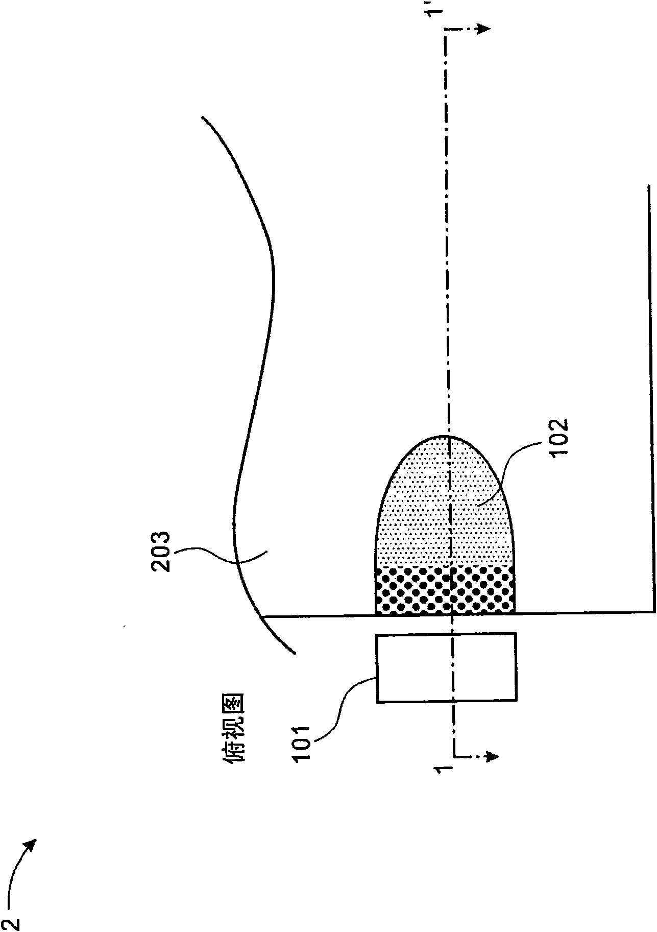
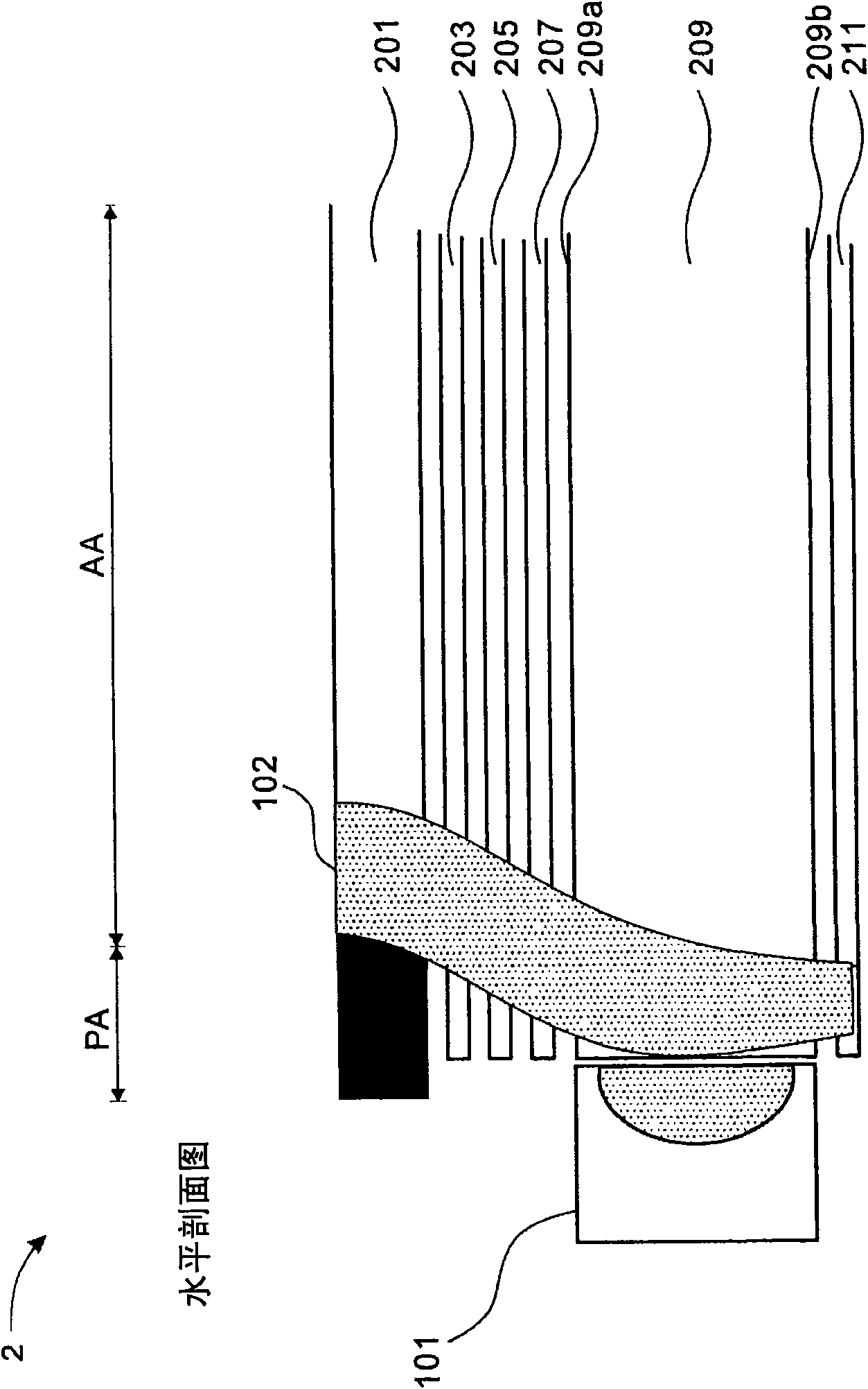
[0021] Figure 4 It is a schematic top view of a system 3 for displaying images according to a specific embodiment of the present invention. Figure 5 for along Figure 4 Sectional view of section line 4-4'. Such as Figure 5 As shown, the system 3 includes a display panel 501 including an active area AA and a peripheral area PA, and a light emitting system (backlight structure) 50 located below the display panel 501 . The lighting system 50 includes a light source 401, a light guide 509, and a plurality of optical films. The light guide 509 is located on one side of the light source 401 and below the display panel 501 . The light guide 509 has a first side 509 a facing the display panel 501 and a second side 509 b op...


PUM


Abstract

The present invention discloses a system for displaying images, comprising: a light source; a panel including an active area and a peripheral area; a light guide being located at one side of the light source and under the panel, the light guide having a first side facing the panel and a second side opposite to the first side; and a plurality of optical foils, each foil disposed on the first or second side of the light guide, wherein at least one of the optical foil has a hotspot-reducing area in the peripheral area in order to reduce or eliminate a hotspot in front of the light source, wherein the hotspot-reducing area is a cut-out area, a covered area, or combinations thereof.

Description

technical field [0001] The present invention relates to an electronic device, a light emitting system, and a display image system, in particular to an electronic device, a light emitting system, and a display image system with an optical film with a hot spot reduction area, so as to reduce or eliminate system hot spots. Background technique [0002] figure 1 It is a schematic top view of an existing system 2 for displaying images. figure 2 display edge figure 1 Sectional view of line 1-1'. The existing system 2 includes a light source 101 , a display panel 201 including an active area AA and a peripheral area PA, prisms 203 and 205 , a diffuser 207 , a light guide 209 , and a reflector 211 . exist figure 1 In the system 2 of , when the light source 101 is activated, a hot spot 102 is usually generated. The light source 101 can be an LED. Besides that, in figure 1 In the example shown, this prism 203 only shows an optical film. The light guide 209 is located on one s...

Claims


Application Information

Patent Timeline
IPC IPC(8): G09F9/00G09F9/30G09G3/34G02B6/00G02B1/10F21V8/00F21V5/00F21Y101/02H01L33/00H01L33/48
CPCG02B6/005
Inventor S·L·G·突圣E·梵德华
Owner TPO DISPLAY
Why Eureka
Try Eureka