
Electronic mechanism with battery device

A technology of electronic mechanism and battery device, applied in the direction of telephone structure, electrical components, transmission system, etc., can solve the problems of receiving interference, inconvenience, small ground area, etc.

Inactive Publication Date: 2009-10-07
INVENTEC APPLIANCES CORP
View PDF0 Cites 3 Cited by
  • Summary
  • Abstract
  • Description
  • Claims
  • Application Information

AI Technical Summary

Problems solved by technology

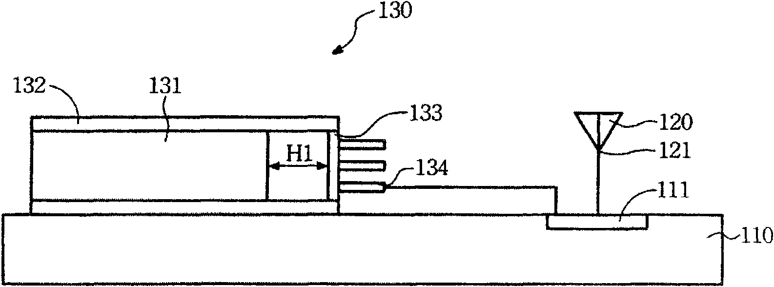
[0004] However, the existing conventional technology has only one ground 111, and its ground area is too small to effectively eliminate the charge, so it will cause the battery body 131 and the antenna 120 to accumulate charges, causing the battery body 131 and the antenna 120 to have a coupling effect, resulting in partial Receive interference, such as communication quality degradation, noise, etc. Therefore, the configuration of the position of the antenna 120 and the position of the battery device 130 must consider whether there will be a coupling effect with each other. Relatively speaking, the configuration of components will have more restrictions, but If the grounding work is done well, this trouble will be greatly reduced
[0005] It can be seen that the above-mentioned existing electronic mechanism with a battery device obviously still has inconvenience and defects in structure and use, and needs to be further improved urgently.
In order to solve the above-mentioned problems, the relevant manufacturers have tried their best to find a solution, but no suitable design has been developed for a long time, and the general products do not have a suitable structure to solve the above-mentioned problems. Urgent problem

Method used


Image

  • Electronic mechanism with battery device
  • Electronic mechanism with battery device

Examples


Embodiment Construction

[0034] In order to further explain the technical means and effects that the present invention adopts to achieve the intended purpose of the invention, the specific implementation, structure, characteristics and details of the electronic mechanism with battery device proposed according to the present invention will be described below in conjunction with the accompanying drawings and preferred embodiments. Its effect is described in detail below.

[0035] The aforementioned and other technical contents, features and effects of the present invention will be clearly presented in the following detailed description of preferred embodiments with reference to the drawings. Through the description of the specific implementation mode, when the technical means and functions adopted by the present invention to achieve the predetermined purpose can be obtained a deeper and more specific understanding, but the accompanying drawings are only for reference and description, and are not used to ...


PUM


Abstract

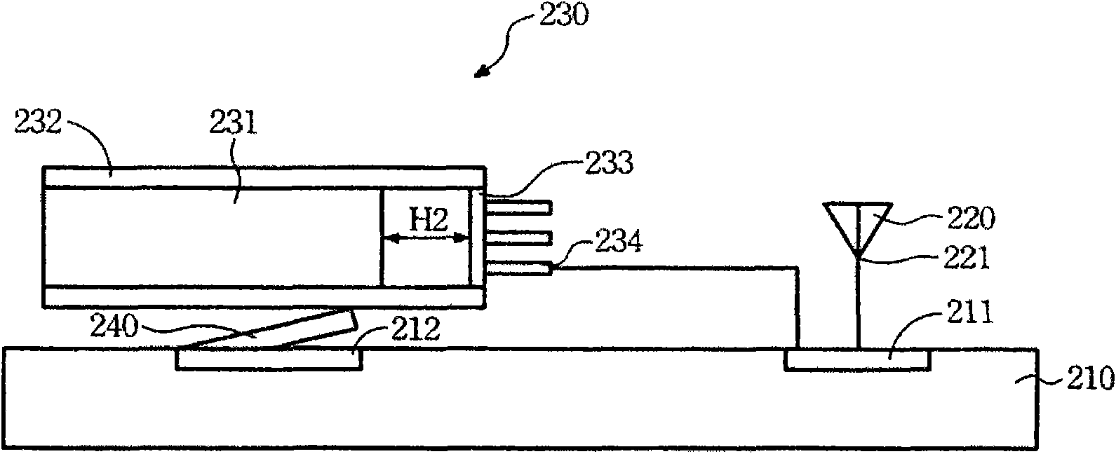
The invention relates to an electronic mechanism with a battery device, which comprises a circuit board, an antenna and a battery device, wherein the circuit board is provided with a first grounding end and a second grounding end; the antenna is provided with a grounding end which is electrically connected with the first grounding end; the battery device comprises a battery body, a battery coating piece, a guard wire circuit board and a battery connector, the periphery of the battery body is coated by one surface of the battery coating piece, one surface of the battery coating piece exceeds a distance from the periphery, the other surface of the battery coating piece is in contact with the second grounding end, and the guard wire circuit board is positioned on the distance which exceeds the periphery of the battery body and is connected with the battery coating piece; and the battery connector is used for connecting the guard wire circuit board and the first grounding end. The second grounding end not only can share the redundant electric charge of the partial battery body, but also can share the redundant electric charge of the partial antenna, and the grounding total area is increased, therefore, the coupling effect can be greatly reduced.

Description

technical field [0001] The invention relates to an electronic mechanism, in particular to an electronic mechanism with a battery device which can reduce the coupling effect produced by the battery and the antenna through the design of the battery. Background technique [0002] see figure 1 As shown, it is a schematic diagram of an electronic mechanism with a battery device in the prior art. The electronic mechanism with a battery device in the prior art includes a circuit board 110, an antenna 120 and a battery device 130; wherein: the circuit board 110 , has a ground 111; the antenna 120 has a ground terminal 121, and the ground terminal 121 is electrically connected to the ground 111 of the circuit board 110; the battery device 130 includes a battery body 131, a battery covering sheet 132, A protection circuit board 133 and a battery connector. [0003] The battery covering sheet 132 is made of a plastic material, one side of which covers the periphery of the battery bod...

Claims


Application Information

Patent Timeline
Patent Type & Authority Applications(China)
IPC IPC(8): H04M1/02H04B1/38H04B1/3883
Inventor 林琦雄林赞西郑伟哲
Owner INVENTEC APPLIANCES CORP
Learn More