Energy absorption device for multi-section vehicles

A technology for energy dissipation and vehicles, which is applied in the direction of buffer vehicles, transportation and packaging, railway car body parts, etc., can solve problems such as not being designed, and achieve the effect of increasing the tensile strength

Active Publication Date: 2013-03-27
VOITH PATENT GMBH
View PDF1 Cites 0 Cited by
  • Summary
  • Abstract
  • Description
  • Claims
  • Application Information

AI Technical Summary

Problems solved by technology

[0012] A further disadvantage of the known solution is manifested in that by providing a randomly designed response trigger in the form of a hypotenuse, the energy dissipation device is not designed to transmit a traction force or at least only conditionally designed to transmit a traction force that occur during normal vehicle operation

Method used


Image

  • Energy absorption device for multi-section vehicles
  • Energy absorption device for multi-section vehicles
  • Energy absorption device for multi-section vehicles

Examples


Embodiment Construction

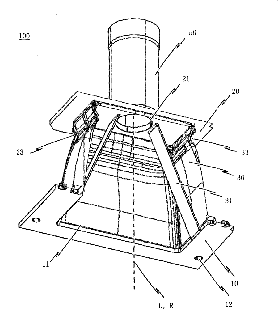
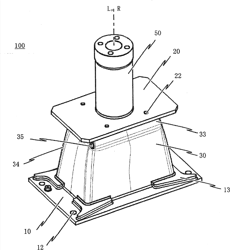
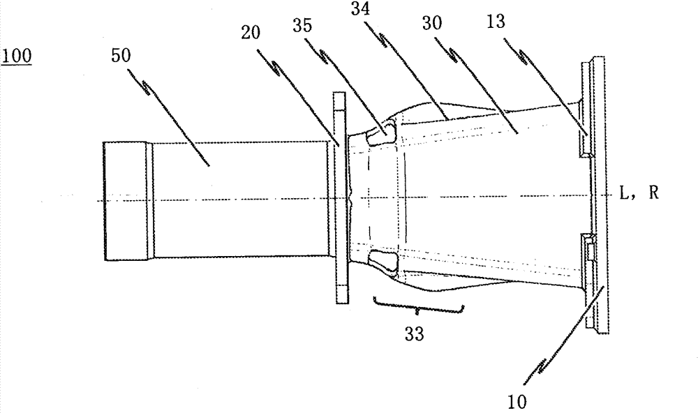
[0048] Figure 1-6 Different views of a preferred embodiment of the energy dissipating device 100 of the present invention are shown. The energy dissipation device 100 is particularly suitable for use as a shock absorber, preferably in combination with a traction device (not shown in detail) to protect the vehicle chassis of a multi-component rail vehicle.

[0049] As shown, the energy dissipating device 100 comprises a first end plate 10 and a second end plate 20, each of which has the function of a force transmission element respectively. In a preferred embodiment of the energy dissipation device 100 according to the invention, each of the two end plates 10 , 20 is respectively configured as a rectangular joint plate. Of course, the invention is obviously not limited to end plates 10, 20 having this design or form.

[0050] The first end plate 10 is designed to attach the energy dissipating device 100 to the main frame (not shown) of the vehicle body, and finally, correspo...


PUM


Abstract

The device (100) has an energy absorbing unit (30) with a connecting body (31), which is formed as a hollow body extending in a longitudinal direction of the absorbing unit. An activation device (32) has a traction unit (32', 32''), which is connected with the body at two opposite fastening positions (F). The traction unit forms a fold (33), which extends in a circumferential direction of the body, when an area of the traction unit is centrally pressed using a manipulators. The area lies between the fastening positions, and the manipulator is pushed into the interior of the body.

Description

technical field [0001] The invention relates to an energy dissipation device for a multi-component vehicle, in particular for a rail vehicle, whereby the energy dissipation device comprises a first end plate, a second end plate and an energy dissipation element in the form of a hollow body , the energy dissipating element extends in the longitudinal direction of the energy dissipating device and is arranged between the first end plate and the second end plate and thereby defines the energy dissipating element upon activation of the energy dissipating device as A folded configuration, the energy dissipating element further comprising a responsive trigger in the form of a folded / raised region extending peripherally at least partially around the periphery of the energy dissipating element configured as a hollow body . The invention also relates to a method for manufacturing such an energy dissipation device. Background technique [0002] One type of energy dissipating device ...

Claims


Application Information

Patent Timeline
Patent Type & Authority Patents(China)
IPC IPC(8): B61D15/06B61G11/16F16F7/12
CPCB61G11/16B61D15/06F16F7/12
Inventor E·贾德
Owner VOITH PATENT GMBH
Why Eureka
Try Eureka