Liquid Crystal Display Device

Inactive Publication Date: 2010-02-11
PANASONIC LIQUID CRYSTAL DISPLAY CO LTD +1
View PDF9 Cites 29 Cited by
  • Summary
  • Abstract
  • Description
  • Claims
  • Application Information

AI Technical Summary

Benefits of technology

[0018]In the mode, a length of the removal preventing pawl may be increased corresponding to th

Problems solved by technology

However, when a liquid crystal panel is curved in one direction by the above-mentioned method, as shown in FIG. 7, due to elasticity of a transparent substrate (a force which acts to return the transparent substrate to an original shape), a gap between the substrates is increased in a zone 70

Method used


Image

  • Liquid Crystal Display Device
  • Liquid Crystal Display Device
  • Liquid Crystal Display Device

Examples


Example

Embodiment 1

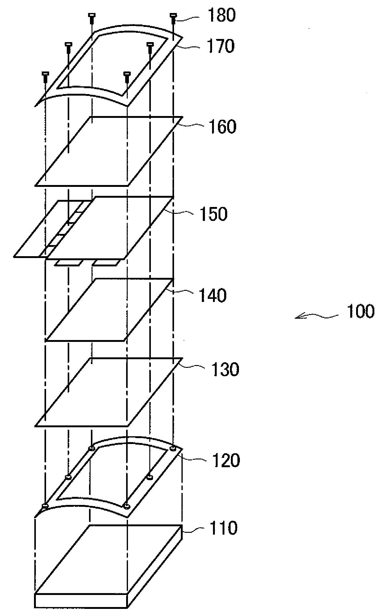
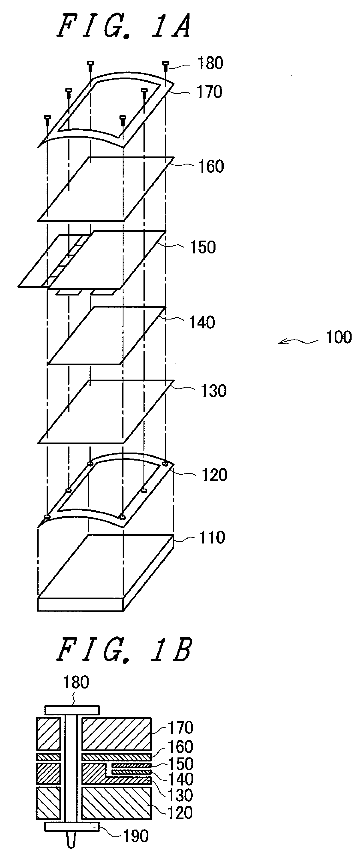
[0031]FIG. 1A and FIG. 1B are views showing constitutional parts of a liquid crystal display device 100 according to an embodiment 1 of the invention.

[0032]As shown in the drawing, the liquid crystal display device 100 includes a backlight 110, a lower frame 120, PC sheets (polycarbonate sheets) 130, 160, a diffusion sheet 140, a liquid crystal panel 150, an upper frame 170, bolts 180 and nuts 190.

[0033]The liquid crystal panel 150 includes a liquid crystal layer and a pair of quadrangular glass substrates having resiliency which sandwiches the liquid crystal layer therebetween. To the liquid crystal panel 150, a drive circuit for controlling voltages applied between pixel electrodes formed on one of the pair of glass substrates and counter electrodes formed on another of the pair of glass substrates, a flexible printed circuit board for transmitting electrical signals and the like to the drive circuit and the like are connected.

[0034]The backlight 110 is a light source ...

Example

Embodiment 2

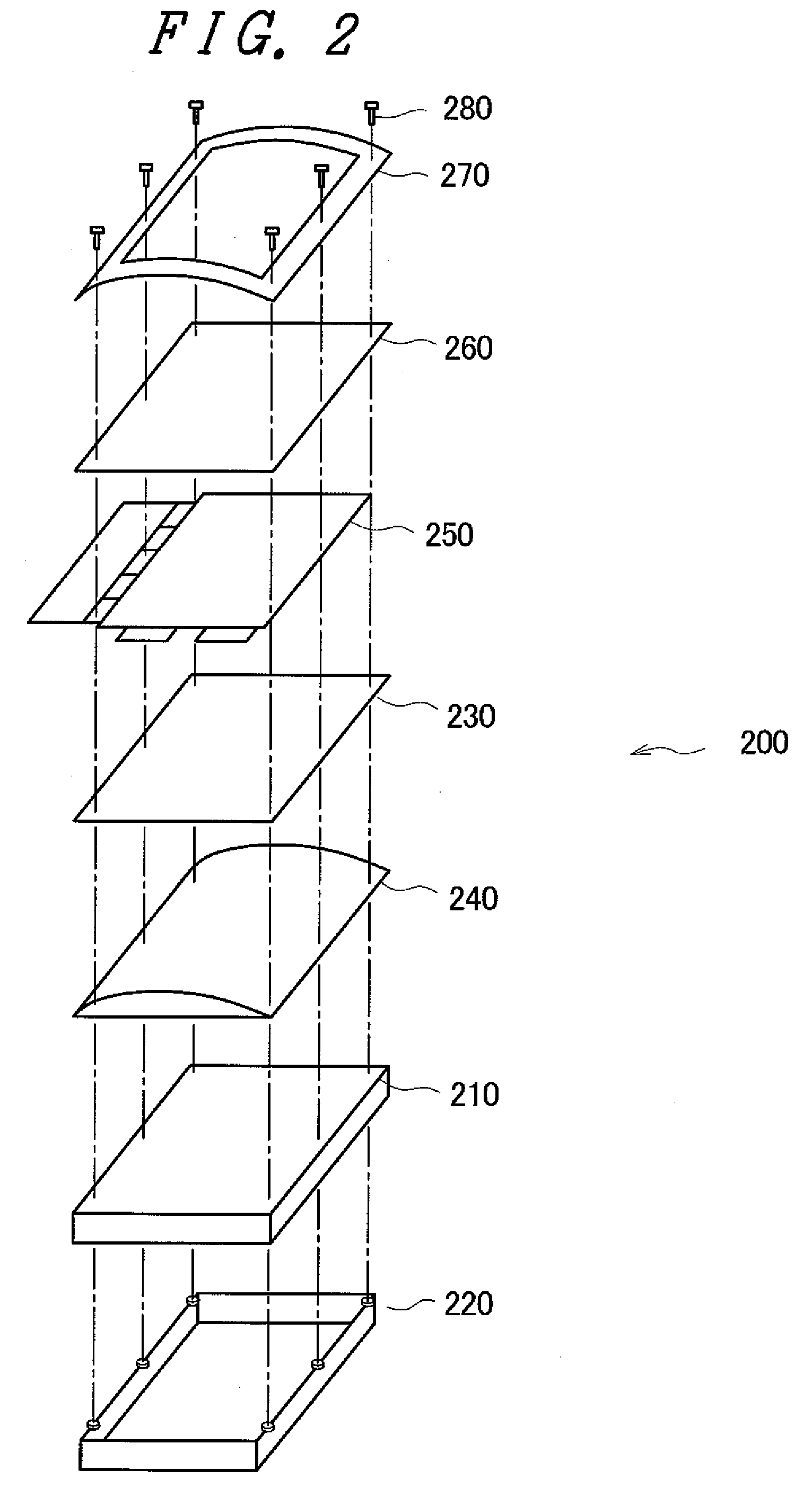
[0047]FIG. 2 is a view showing constitutional parts of a liquid crystal display device 200 according to an embodiment 2 of the invention.

[0048]As shown in the drawing, the liquid crystal display device 200 includes a lower frame 220, a backlight 210, a diffusion plate 240, a PC sheet 230, a liquid crystal panel 250, a PC sheet 260, an upper frame 270, bolts 280 and nuts (not shown in the drawing).

[0049]The liquid crystal panel 250 includes a liquid crystal layer and a pair of quadrangular glass substrates having resiliency which sandwiches the liquid crystal layer therebetween.

[0050]The backlight 210 is a light source which is arranged on a back surface side of the liquid crystal panel 250. The backlight 210 has a back surface side thereof supported by the lower frame 220.

[0051]The PC sheets 230, 260 are formed of a transparent sheet made of polycarbonate which has resiliency. The PC sheet 230 is arranged on a back surface side of the liquid crystal panel 250, while the ...

Example

Embodiment 3

[0060]FIG. 3 is a view showing constitutional parts of a liquid crystal display device 300 according to an embodiment 3 of the invention.

[0061]As shown in the drawing, the liquid crystal display device 300 includes a backlight 310, a pipe 390, a diffusion sheet 340, a liquid crystal panel 350, an upper frame 370, push plates 372, bolts 380 and nuts (not shown in the drawing).

[0062]The liquid crystal panel 350 includes a liquid crystal layer and a pair of quadrangular glass substrates having resiliency which sandwiches the liquid crystal layer therebetween.

[0063]The backlight 310 is a light source which is arranged on a back surface side of the liquid crystal panel 350.

[0064]The diffusion sheet 340 is formed of a transparent or a semi-transparent sheet having resiliency and is arranged between the backlight 310 and the liquid crystal panel 350. The diffusion sheet 340 diffuses light emitted toward the liquid crystal panel 350 from the backlight 310.

[0065]The pipe 390, the...


PUM


Abstract

A liquid crystal display device includes: a liquid crystal panel which includes a liquid crystal layer and a pair of resilient substrates which sandwiches the liquid crystal layer therebetween; and a curving holding means (a lower frame, an upper frame, a plurality of bolts, and a plurality of nuts) which clamps an outer peripheral portion of the liquid crystal panel from a front surface and a back surface of the liquid crystal panel so as to hold the liquid crystal panel in a state that the liquid crystal panel is curved in one direction, wherein a clamping force applied to a non-curved outer peripheral portion of the liquid crystal panel by the curving holding means is set larger than a clamping force applied to a curved outer peripheral portion of the liquid crystal panel by the curving holding means.

Description

[0001]The present application claims priority from Japanese applications JP 2008-205790 filed on Aug. 8, 2008, the content of which is hereby incorporated by reference into this application.BACKGROUND OF THE INVENTION[0002]1. Field of the Invention[0003]The present invention relates to a liquid crystal display device, and more particularly to a liquid crystal display device which includes a curved liquid crystal panel.[0004]2. Description of the Related Art[0005]In the manufacture of a curved-face display using a liquid crystal panel, it is advantageous to adopt the following method for relatively easily manufacturing the curved-face display. That is, a liquid crystal panel having resiliency by making thicknesses of a pair of transparent substrates (for example, glass substrates) which sandwiches a liquid crystal layer therebetween small is prepared. Then, the liquid crystal panel is curved in one direction along a suitable curved member and, at the same time, sides of the liquid cr...

Claims


Application Information

Patent Timeline
IPC IPC(8): G02F1/1333
CPCG02F1/133305G02F2001/13332G02F1/133308G02F1/13332
Inventor KAGANEZAWA, NOBUYUKI
Owner PANASONIC LIQUID CRYSTAL DISPLAY CO LTD
Why Eureka
Try Eureka