Display device and process for production thereof

a technology of display device and process, applied in the field of display device, can solve the problems of flickering and low luminance of light source, visual load on human eyes, difficulty in recognizing characters, etc., and achieve the effect of reducing display irregularity and cos

Inactive Publication Date: 2005-04-05
CANON KK
View PDF11 Cites 35 Cited by
  • Summary
  • Abstract
  • Description
  • Claims
  • Application Information

AI Technical Summary

Benefits of technology

In view of the state of prior art as described above, a principal object of the present invention is to provide an (electrophoretic) display device capable of reducing display irregularity and yet capable of production at a reduced cost.

Problems solved by technology

However, such liquid crystal display devices are still accompanied with problems of visual load on human eyes, such as difficulty of recognizing characters on display depending on a viewing angle or due to reflection light, and flickering and low luminance of light sources.
When such an electrophoretic display device is repetitively used for a long period, the density distribution of the electrophoretic particles 31 is liable to be biased or ununiform, thus causing display irregularity.
However, in such a known electrophoretic display device wherein the dispersion layer is divided into small sections (cells) by forming partitioning walls at certain intervals for obviating ununiform density distribution of electrophoretic particles, the electrophoretic particles have to be evenly distributed to respective cells, but such distribution is not easy.
Further, a series of production steps including formation of partitioning walls on a substrate, uniform distribution of a display medium comprising a mixture of electrophoretic particles and an insulating liquid and sealing of the display medium, requires much time and a substantial cost.
Further, in the case of color display using plural colors of electrophoretic particles and / or insulating liquid sealed within cells separated by partitioning walls, the mixing of colors between adjacent cells is liable to be caused during the production process, so that selective filling of electrophoretic particles or insulating liquid of a desired color is difficult and therefore a further difficulty is encountered.

Method used


Image

  • Display device and process for production thereof
  • Display device and process for production thereof
  • Display device and process for production thereof

Examples


first embodiment

(First Embodiment)

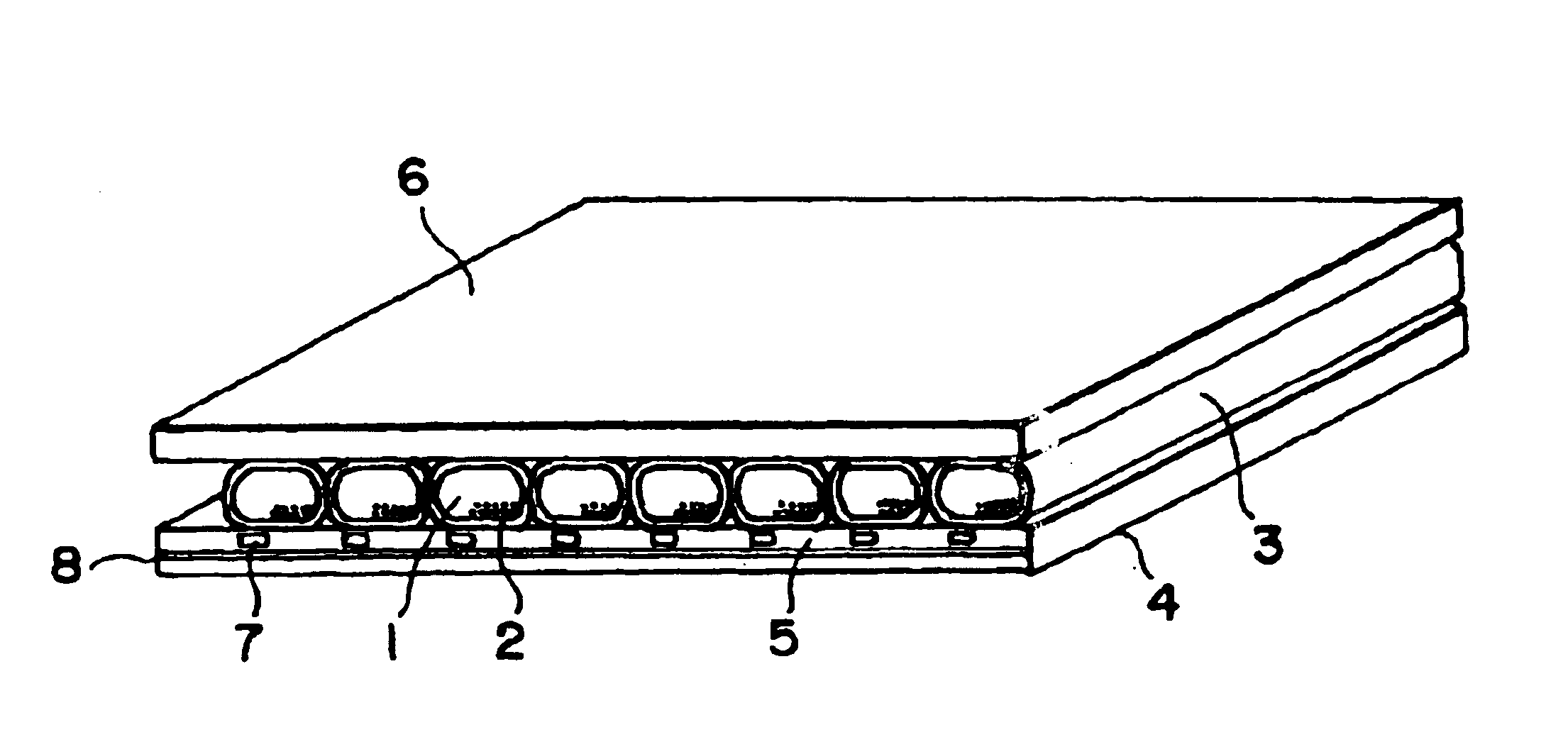
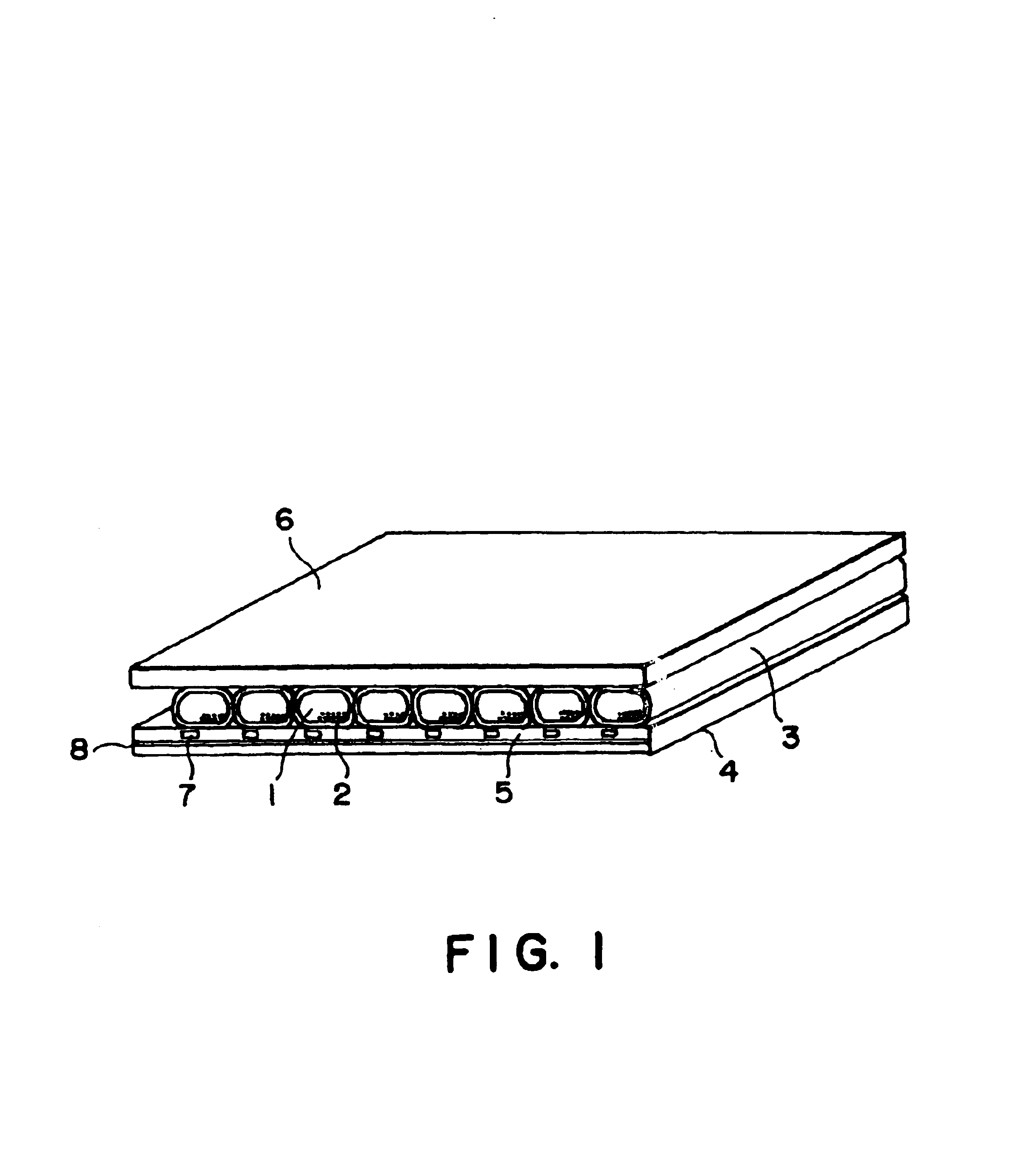
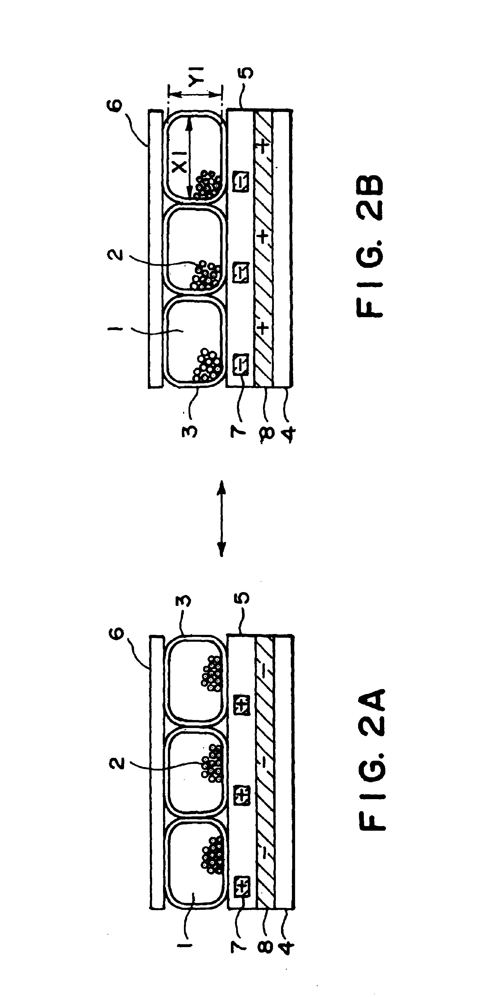
FIG. 1 is a perspective view of an electrophoretic display device according to an embodiment of the present invention, and FIGS. 2A and 2B are partial sectional views thereof for illustrating an operation principle thereof.

Referring to these figures, the display device includes a display medium comprising a transparent insulating liquid 1 and colored electrophoretic particles 2, and light-transmissive tubes 3 each containing the display medium and sandwiched between a first substrate 4 and a second substrate 6. Further, an insulating layer 5 is disposed on the first substrate 4, and the tubes 3 are held between the insulating layer 5 and the second substrate 6. Below the insulating layer 5, second electrodes 7 are locally formed, and first electrodes 8 (only one being shown) are formed further therebelow on the first substrate 4. For convenience of illustration of an inner state, FIG. 1 shows a state of the display device of which the peripheral sealing structure h...

example 1

A display device of 5 cm-square in plane size was produced in the following manner through a process as illustrated in FIG. 8A and FIGS. 9A-9E.

First of all, a cylindrical light-transmissive tube 3 of PET having a length of 5 cm, a thickness of 3-8 μm and an inner diameter of 200 μm was filled with a display medium which was a 30:1 (by weight)-mixture of a transparent insulating liquid 1 of silicone oil and black electrophoretic particles 2 of a polystyrene-carbon mixture having particle sizes of ca. 1-2 μm in a manner as illustrate in FIG. 8A, i.e., by dipping one end of the tube 3 into a bath of the display medium under sufficient stirring in a vessel 21 and sucking from the other and the tube 3. After the filling, both ends of the tube 3 were sealed up by heating.

Then, on a light-transmissive first substrate 4 of 200 μm-thick PET film, an ITO film was formed and patterned into first electrodes 8 in the form of 190 μm-wide stripes (only one thereof being shown in FIG. 9A) arranged ...

example 2

A display device was prepared through a process as illustrated in FIGS. 10A-10E.

Tubes 3 were filled with the same display medium and in the same manner as in Example 1. Further, a first substrate 4 was provided with first electrodes 8, an insulating layer 5 and second electrodes 7 as shown in FIGS. 10A-10B in the same manner as in Example 1.

Then, the above-prepared tubes 3 filled with the display medium were arranged in a similar manner as in Example 1 except that they were arranged with their longitudinal directions parallel to the extension direction of the first electrodes 8 (FIG. 10C). Thereafter, a second substrate 6 was disposed thereabove (FIG. 10D) and the substrates 4 and 6 were bonded to each other in the same manner as in Example 1 to form a structure shown in FIG. 10E, which was then provided with voltage application means to complete a display device.

The thus-prepared display device was driven by application of ±50 volts between the electrodes, whereby a display with no...


PUM

PropertyMeasurementUnit
thicknessaaaaaaaaaa
specific gravityaaaaaaaaaa
diameteraaaaaaaaaa

Abstract

A display device includes a first substrate and a second substrate disposed opposite to each other, and a display medium including an insulating liquid and electrophoretic colored particles dispersed therein and disposed between the first and second substrates. A first electrode and a second electrode are provided for applying a voltage to the display medium so as to move the colored particles between the first and second electrodes to effect a display depending on a voltage applied to the first and second electrodes. The electrophoretic colored particles are distributed uniformly without localization by incorporating the display medium in a plurality of light-transmissive tubes, and disposing and fixing the plurality of tubes in intimate contact with each other between the first and second substrates.

Description

FIELD OF THE INVENTION AND RELATED ARTThe present invention relates to a display device of the type wherein electrophoretic particles or charged migrating particles are moved to effect a display, and a process for producing such a display device.In recent years, accompanying the progress of data processing apparatus, there has been an increasing demand for a display device requiring a small power consumption and a small thickness, and extensive study and development have been made on devices satisfying such a demand. Among these, a liquid crystal display device wherein an alignment of liquid crystal molecules is electrically controlled to change optical characteristics has been extensively developed and commercialized as a display device satisfying the demand described above.However, such liquid crystal display devices are still accompanied with problems of visual load on human eyes, such as difficulty of recognizing characters on display depending on a viewing angle or due to refle...

Claims


Application Information

Patent Timeline
Patent Type & Authority Patents(United States)
IPC IPC(8): G02F1/01G02B26/02G02F1/167G02F1/16757G02F1/1679G09G5/37
CPCG02B26/004G02F1/167G02F2203/34G02F1/134363G02F1/16757G02F1/1679
Inventor MIURA, NAOKOMOTOI, TAIKOMATSUDA, HIROSHIIKEDA, TSUTOMU
Owner CANON KK
Why Eureka
Try Eureka