
Light source unit, backlight unit and display apparatus having the same

Inactive Publication Date: 2008-06-26
CITIZEN ELECTRONICS CO LTD
View PDF3 Cites 29 Cited by
  • Summary
  • Abstract
  • Description
  • Claims
  • Application Information

AI Technical Summary

Benefits of technology

[0046]As has been stated above, light from a plurality of LEDs having different emission spectrum peak wavelengths is diffused in a specific direction by a light mixing member provided with anisotropic diffusing elements. Therefore, color mixing can be promoted, and it is possible to obtain white light with reduced color irregularity.
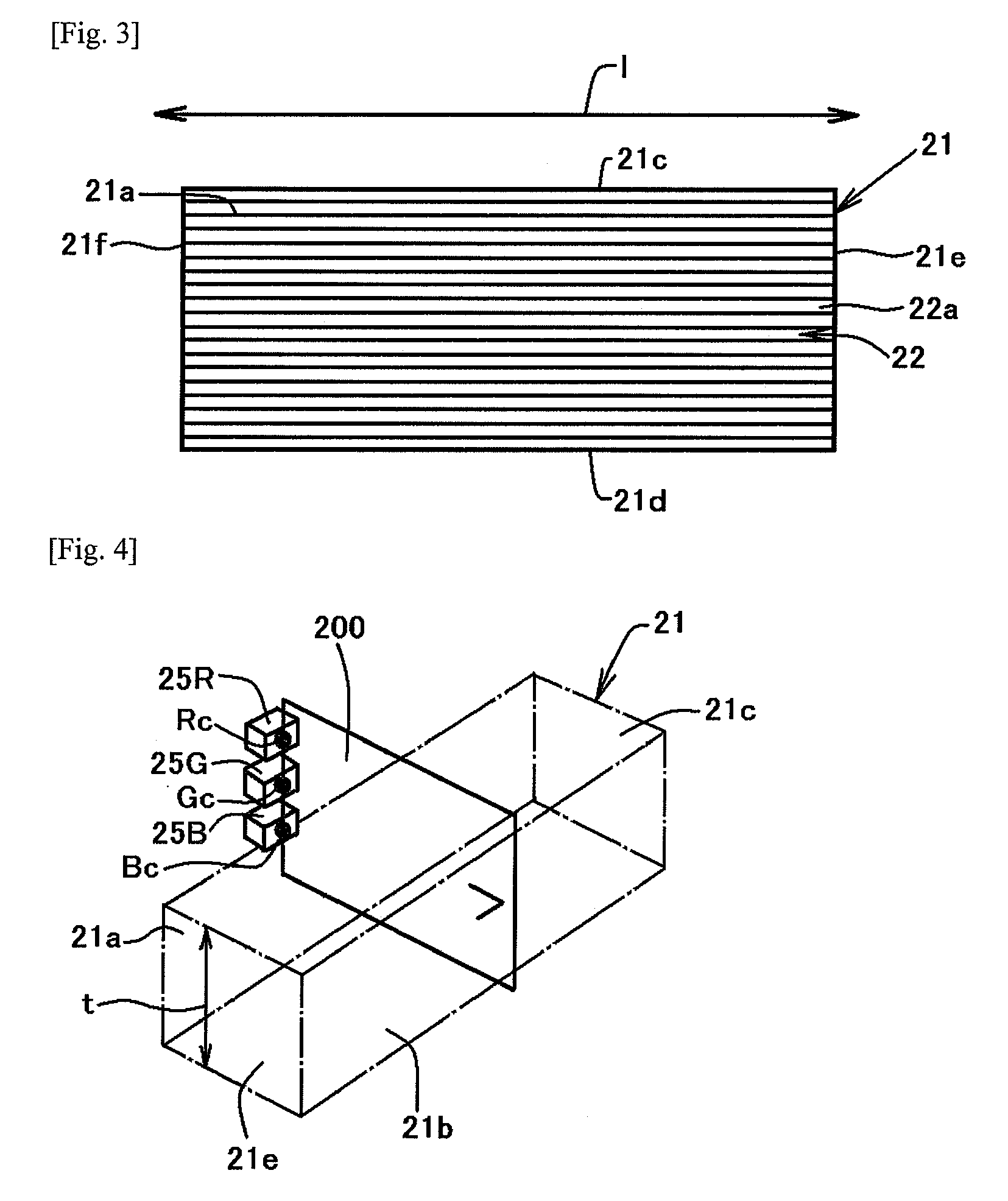
[0047]Particularly, in the present invention, centers of light-emitting surfaces of the LEDs are configured to be in the same plane that is substantially perpendicular to the exit surface and substantially parallel to the thickness direction of the light mixing member. Therefore, light emitted from the center of the light-emitting surface of each LED, which has a strong emission intensity, can be diffused effectively. Thus, white light with further reduced color irregularity can be obtained.
[0048]Thus, it is possible accordingly to the present invention to provide a light source unit capable of obtaining white light with reduced color irregularity and a backlight unit and a display apparatus having the light source unit.

Problems solved by technology

The technique disclosed in the above-described Japanese Patent Application Publication No. 2005-183124 suffers, however, from the following problem.
Accordingly, it is deemed difficult to set such that the intensity of exiting light becomes uniform over the entire light-emitting surface.
Therefore, color irregularity is likely to occur near the entrance surface of the lightguide plate.

Method used


Image

  • Light source unit, backlight unit and display apparatus having the same
  • Light source unit, backlight unit and display apparatus having the same
  • Light source unit, backlight unit and display apparatus having the same

Examples


Embodiment Construction

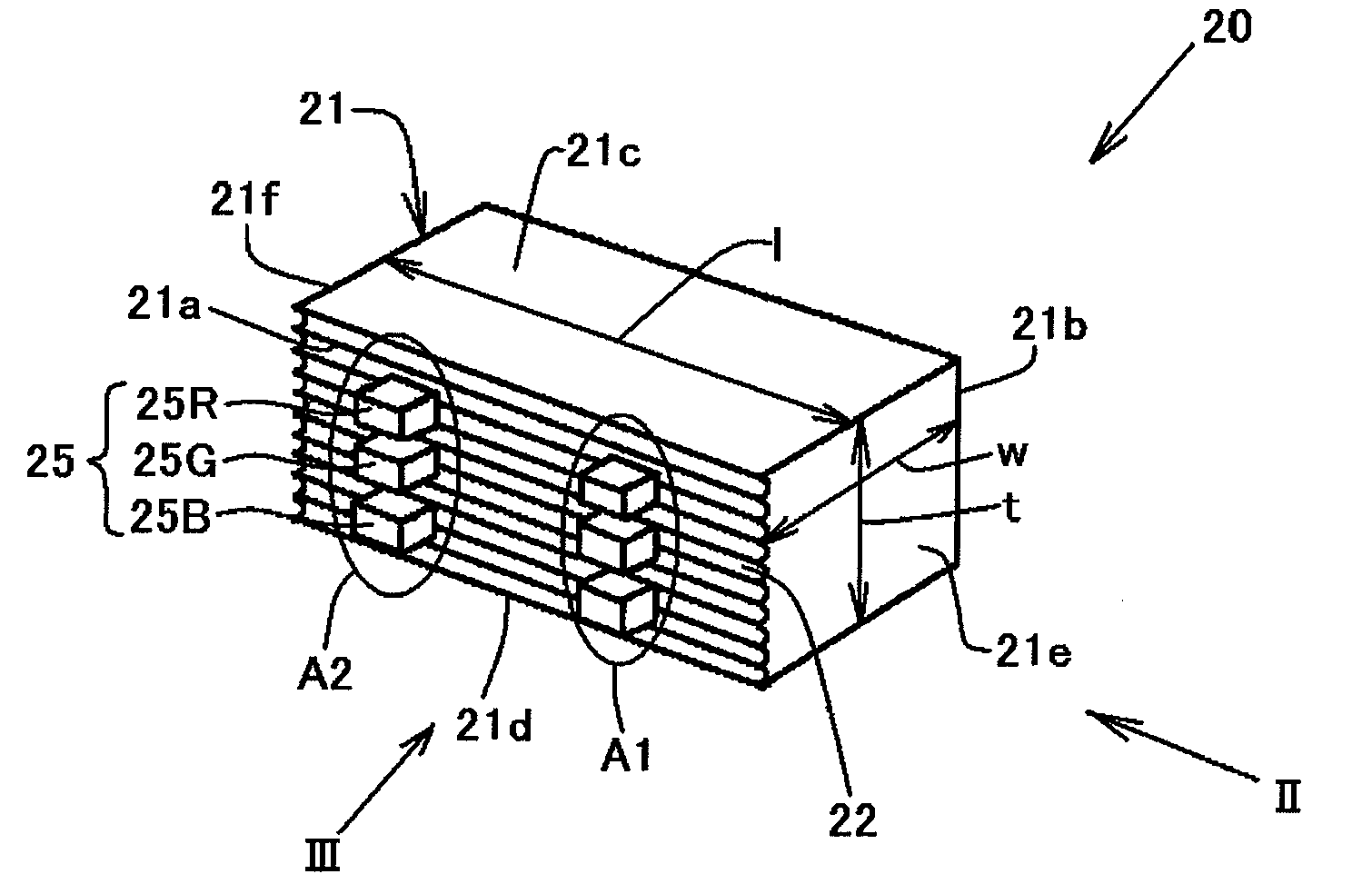
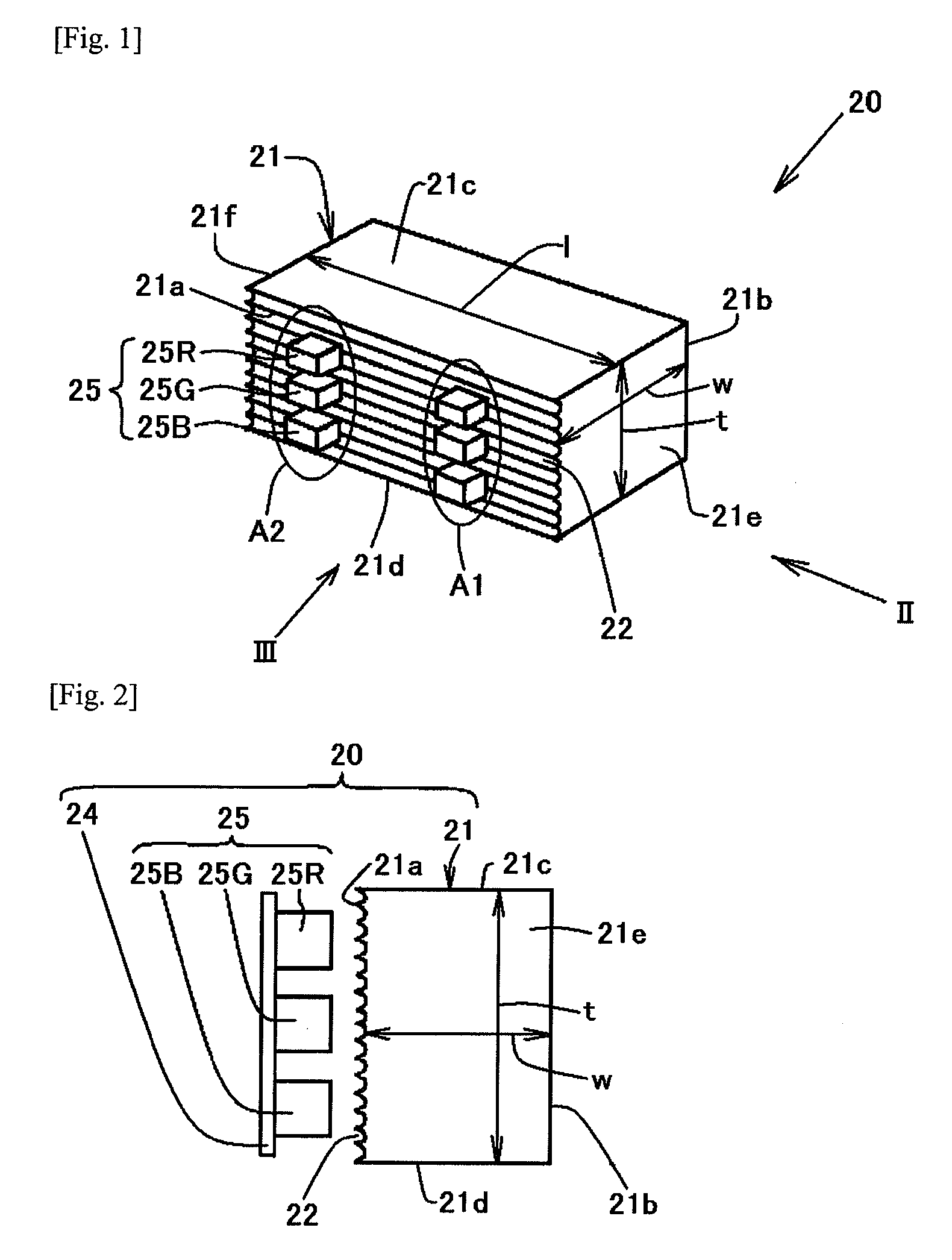
[0070]An embodiment of the present invention will be explained below with reference to FIGS. 1 to 9d. In the following explanation, the term “substantially” is used in such phrases as “substantially perpendicular” and “substantially parallel”. The reason for this is as follows. The configuration of constituent members used in the present invention is not limited to a rectangular parallelepiped but may include a shape partly having inclined surfaces, for example. The term “substantially” is also used to explain constituent members in consideration of errors in machining accuracy.

[0071]As shown in FIGS. 1 and 2, a light source unit 20 in this embodiment has a plurality of LED sets 25 and a light mixing member 21 that mixes different colors of light i.e., lights having different emission spectrum peak wavelengths from the LED sets 25 entering through an entrance surface 21a and that emits the color-mixed light from an exit surface 21b. The light mixing member 21 in this embodiment is o...


PUM


Abstract

A light source unit capable of obtaining white light with reduced color irregularity includes a plurality of light-emitting diodes (25R, 25G and 25B) having different emission spectrum peak wavelengths, and a light mixing member (21) that receives lights from the light-emitting diodes through an entrance surface (21a) and that allows lights to mix together before exiting through an exit surface (21b). The light mixing member (21) has anisotropic diffusing elements (22) that diffuse incident lights from the light-emitting diodes in a specific plane to effect light mixing.

Description

[0001]This application claims priority under 35 U.S.C. §119 to Japanese Patent application No. JP2006-339764 filed Dec. 18, 2006, the entire content of which is hereby incorporated by reference.TECHNICAL FIELD[0002]The present invention relates to a light source unit that mixes a plurality of different colors of light from LED (light-emitting diode) light sources. The present invention also relates to a backlight unit and a display apparatus that have the light source unit.RELATED CONVENTIONAL ART[0003]Liquid crystal displays are widely used as thin display apparatus in small-sized portable devices, such as mobile phones and digital cameras, and also in medium- to large-sized image and picture displaying devices such as projectors, notebook personal computers, and liquid crystal monitors. Owing to recent improvements in emission efficiency of LEDs, the application range of LED light sources is expanding rapidly. For example, there have been developed liquid crystal display apparatus...

Claims


Application Information

Patent Timeline
IPC IPC(8): G02F1/1335F21V9/00F21V7/04
CPCG02B6/0016G02B6/0023G02B6/0025G02B6/0028G02F2001/133613G02F1/133603G02F1/133609G02F2001/133607G02B6/0068G02F1/133607G02F1/133613
Inventor NOBA, KOYA
Owner CITIZEN ELECTRONICS CO LTD
Learn More