
LED spotlight

Inactive Publication Date: 2009-02-26
NEC LIGHTING
View PDF4 Cites 69 Cited by
  • Summary
  • Abstract
  • Description
  • Claims
  • Application Information

AI Technical Summary

Benefits of technology

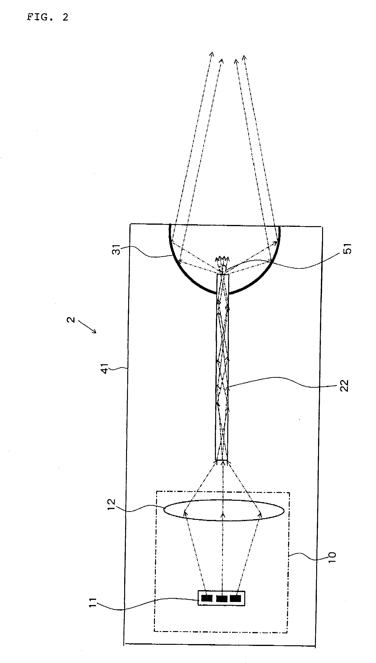
[0022]According to the present invention, passing light through the rod lens including an exit end having a small area can provide a point light source formed of a complete diffusion light, and it becomes easy to design a spotlight.
[0023]Also, according to the present invention, even when LEDs of three colors, R, G and B are used, light from an LED is used as an exciting light, and even when white light is obtained from fluorescent material, light is passed through the rod lens, thereby color irregularity can be reduced.
[0024]The present invention uses a configuration in which a light from an LED is collected at one point by the light condensing means, and at a position where the focal point is formed, the rod lens is installed, and ahead of the rod lens including the exit end having a small area, the reflector or the lens is provided to condense a light. According to this configuration, the invention laid open in this application can provide the point light source formed of a complete diffusion light, and can sufficiently mix colors, therefore there is an advantage in which a spotlight of white light without color irregularity is provided.

Problems solved by technology

Accordingly, it is difficult to control light distribution by using a reflector, as compared to using compared to the case of an electric bulb.
Further, because light from an LED has a high directivity and a sharp spectrum, the light is difficult to mix due to the nature of the LED.
However, none of the documents state that irradiated light is collected into a spotlight.

Method used


Image

  • LED spotlight
  • LED spotlight
  • LED spotlight

Examples


Embodiment Construction

)

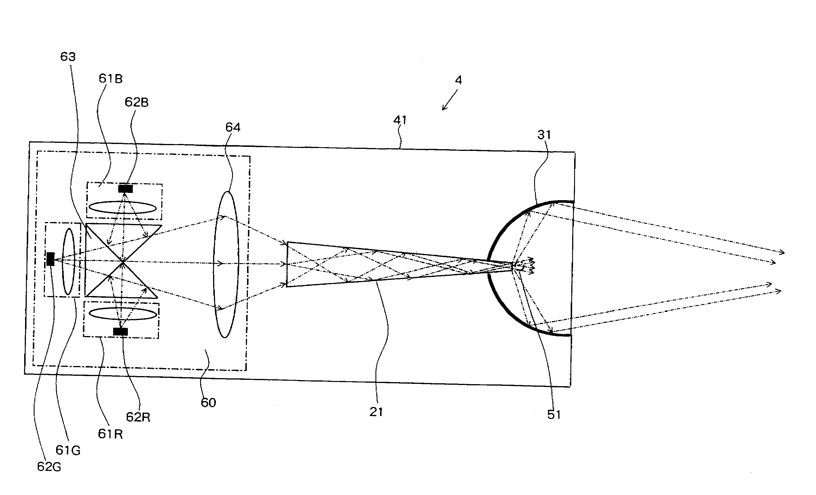
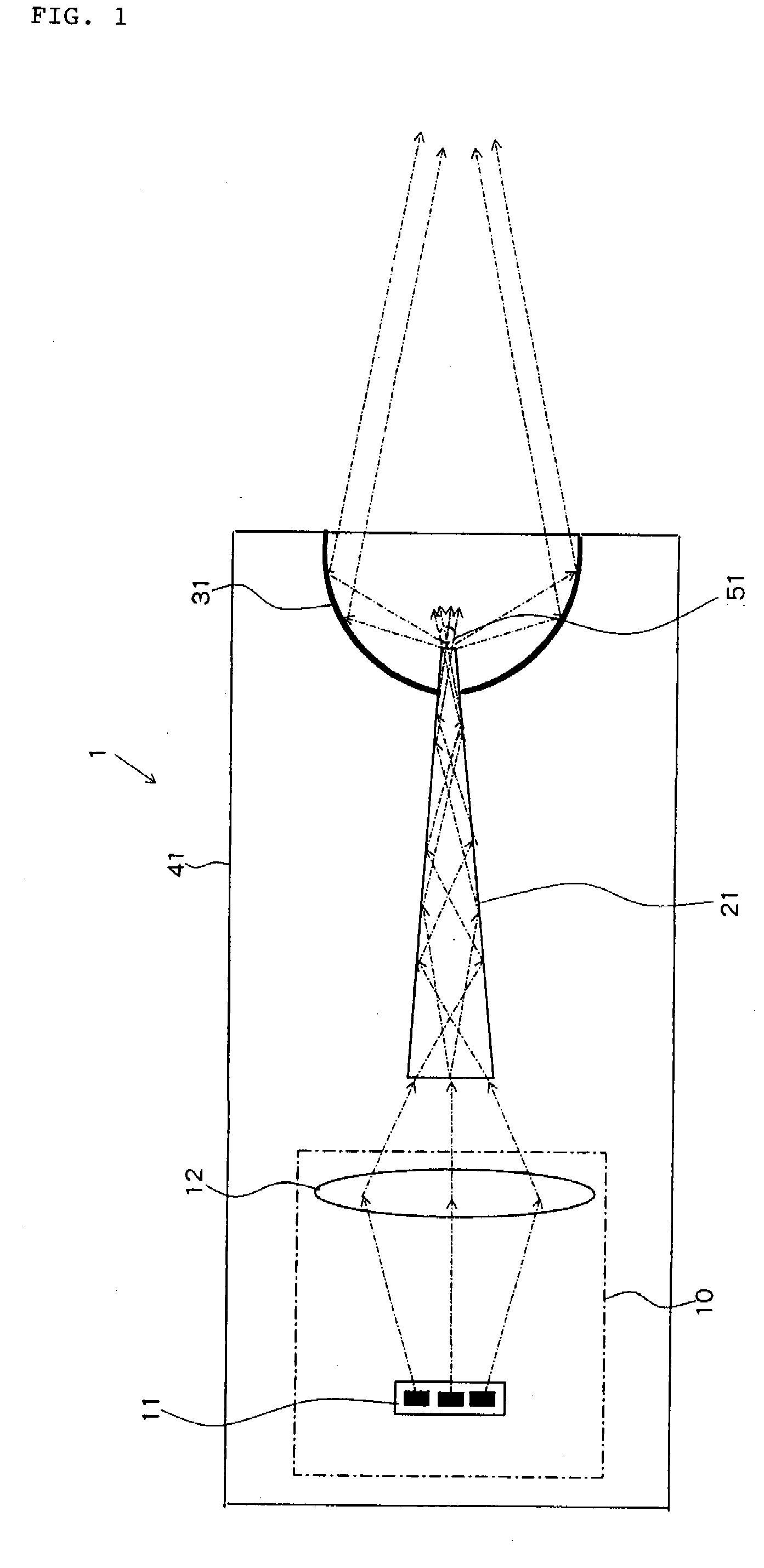
[0029]Next, a first exemplary embodiment of the present invention will be described with reference to the accompanying drawings. FIG. 1 is a schematic side view of an LED spotlight of the first exemplary embodiment of the present invention.

[0030]LED spotlight 1 of the first exemplary embodiment of the present invention includes RGB-LED light source 11, light source unit 10, pyramid rod lens 21, reflector 31, and casing 41.

[0031]Light source unit 10 has first condenser lens 12. First condenser lens 12 is a first light condensing means for condensing light beams of mixed color projected from RGB-LED light source 11 on an entrance face of rod lens 21. Pyramid rod lens 21 is a pyramid-shaped lens whose cross-section converges toward an exit face. Reflector 31 condenses rays of exiting light exiting from the exit face of pyramid rod lens 21 to form point light source 51. Here, the first light condensing means has been described as a condenser lens, but a reflector may be used.

[0032]Elec...


PUM


Abstract

An LED spotlight includes: a light source unit including an RGB-LED light source composed of R, G and B LEDs, and a condenser lens for condensing light beams of mixed color projected from the RGB-LED light source on an entrance end face of a rod lens; a pyramid rod lens whose cross-sectional area converges from an entrance end face to an exit end face; and a reflector for condensing rays of exiting light exiting as a point light source from the exit face of the pyramid rod lens on an axial line of the pyramid rod lens. A light beam incident on the pyramid rod lens progresses while repeatedly internally reflected several times, thereby brightness irregularity at the exit end of the rod lens is lowered, and color mixture is accelerated, so that a light beam is emitted as a point light source of white light whose color is observed as the same color, seen from any direction, and the light beams are condensed as a spotlight on the axial line of the pyramid rod lens by the reflector.

Description

[0001]This application is based upon and claims the benefit of priority from Japanese patent application No. 2007-070521, filed on Mar. 19, 2007, the disclosure of which is incorporated herein in its entirety by reference.BACKGROUND OF THE INVENTION[0002]1. Field of the Invention[0003]The present invention relates to an LED spotlight having an LED as a light source, particularly to an LED spotlight including a rod lens.[0004]2. Description of the Related Art[0005]An LED (light-emitting diode) has features such as low power consumption, long service life, low heat generation, quick response, and space saving. Accordingly, LED have been widely used in illumination applications in which an LED is used as a light source and LED have found practice use in applications from a traffic lights to a headlights of automobiles.[0006]On the one hand, light from an LED has a characteristic in which the light intensity changes depending on a light exit angle. Accordingly, it is difficult to contro...

Claims


Application Information

Patent Timeline
IPC IPC(8): F21V13/02F21K7/00F21V7/00F21K99/00
CPCF21S48/1154F21S48/1159F21V7/0091F21W2101/10F21S48/1127F21Y2113/00F21V2200/00F21S48/1241F21Y2101/02F21S41/12F21S41/143F21S41/148F21S41/24F21Y2115/10F21S41/147F21S41/20F21W2102/00
Inventor KON, SHUSAKU
Owner NEC LIGHTING
Learn More