
Semi-continuous treatment of produced water with boiler flue gas

Active Publication Date: 2017-03-02
CONOCOPHILLIPS CO
View PDF16 Cites 3 Cited by
  • Summary
  • Abstract
  • Description
  • Claims
  • Application Information

AI Technical Summary

Benefits of technology

The patent describes a system and process for cleaning produced water using heat energy that would otherwise be wasted. It achieves this by using a semi-continuous process where water is continuously run until it reaches a point where contaminants and sediment in the water reach a maximum level. The contents are then purged and the vessel is refilled with untreated water. The system uses gas redistributors to improve contact and heat transfer between the flue gas and the untreated water, resulting in efficient heat transfer. The overhead gas is cooled and sent to a knockout pot where flue gas is vented and the treated water is removed. The treated water is low in contaminants and can meet the specifications of higher efficiency boilers, reducing the cost of boiler fuel gas. Overall, the system is cost-effective and does not require large amounts of chemicals or expensive specialty equipment.

Problems solved by technology

The effective production of hydrocarbon reservoirs containing heavy oils or unconventional oils presents significant challenges.
Extraction of these high viscosity hydrocarbons is difficult due to their relative immobility at reservoir temperature and pressure.
These properties make it difficult to simply pump the unconventional oil out of the ground.
Such hydrocarbons may be quite thick and have a consistency similar to that of peanut butter or heavy tars, making their extraction from reservoirs difficult.
However, currently known and utilized methods for treating heavy oil field produced waters in order to generate high quality steam for down-hole are not entirely satisfactory for a few reasons:most physical chemical treatment systems are quite extensive, are relatively difficult to maintain, and require significant operator attention;treatment systems require large amounts of expensive chemicals, many of which require special attention for safe handling, and which present safety hazards if mishandled as well as environmental hazards; and,a large quantity of unusable hot water is created, and the energy from such water must be recovered, as well as the water itself, in order to maintain an economic heat and material balance in operations.

Method used


Image

  • Semi-continuous treatment of produced water with boiler flue gas
  • Semi-continuous treatment of produced water with boiler flue gas
  • Semi-continuous treatment of produced water with boiler flue gas

Examples


Embodiment Construction

[0052]A novel system and method for treating water on an oil pad is disclosed. Waste flue gas from, e.g., a once-through steam generator is used to vaporize untreated water in a contacting vessel. Un-vaporized solids and sediments remain in the contact vessel, and the vapor routed as needed.

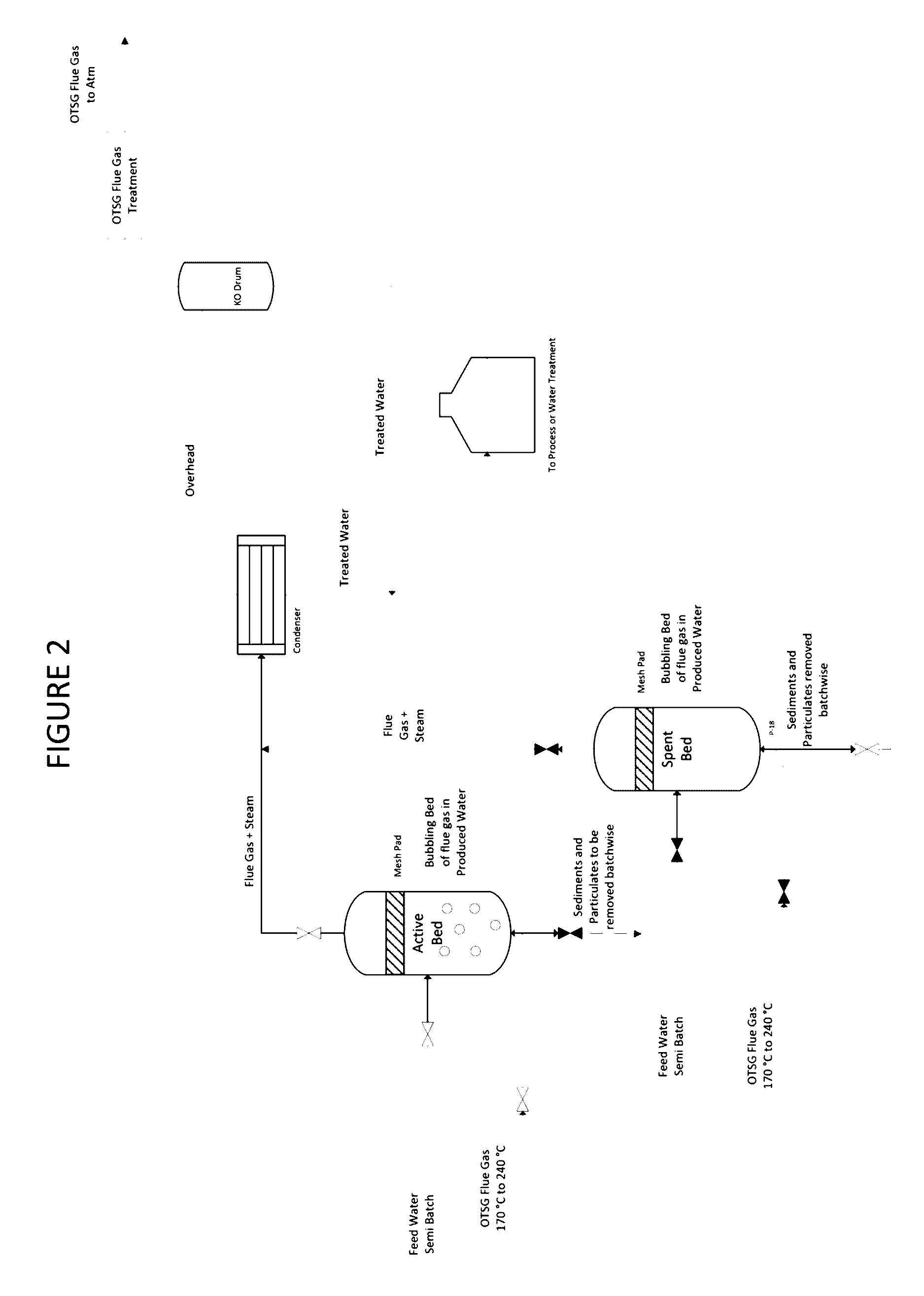
[0053]One embodiment of the presently disclosed system is shown in FIG. 2. In this system, heated flue gas from an OTSG is introduced into one or more contacting vessels having a batch of untreated water. The flue gas has a temperature range of at least 170° C. to 240° C., which is high enough to vaporize water to form steam.

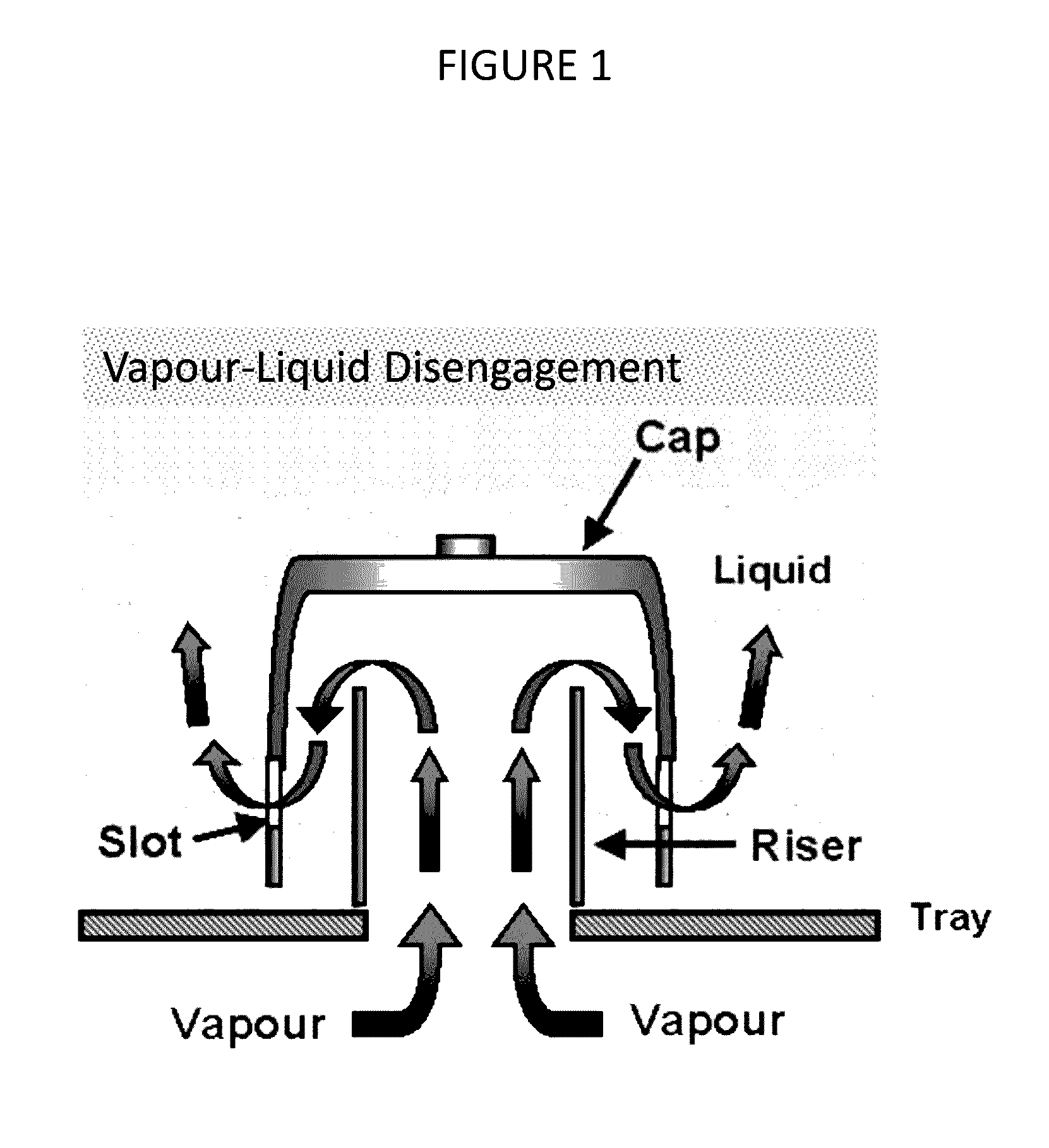
[0054]The contacting vessel is shown in more detail in FIG. 3. The bottom of the contacting vessel 300 has a distributor plate fitted with bubble caps 301. Heated flue gas rises through the bubble caps to bubbling through the untreated water in the contacting area 302 of the contacting vessel 300, resulting in the vaporization of the untreated water.

[0055]As the flue gas and ...


PUM

PropertyMeasurementUnit
Temperatureaaaaaaaaaa

Abstract

Systems and methods utilize heated waste flue gas to treat water. The heated waste flue gas, which may come from a steam generator, bubbles through untreated water to vaporize the untreated water and separate out solids and other contaminants before subsequent condensing. The steam generator may receive resulting treated water to produce steam for injection.

Description

PRIOR RELATED APPLICATIONS[0001]This application is a non-provisional application which claims benefit under 35 USC §119(e) to U.S. Provisional Application Ser. No. 62 / 210,180 filed Aug. 26, 2015, entitled “SEMI-CONTINUOUS TREATMENT OF PRODUCED WATER WITH BOILER FLUE GAS,” which is incorporated herein in its entirety.FIELD OF THE DISCLOSURE[0002]The invention relates to treatment methods for water, particularly produced water from oil fields.BACKGROUND OF THE DISCLOSURE[0003]The effective production of hydrocarbon reservoirs containing heavy oils or unconventional oils presents significant challenges. Extraction of these high viscosity hydrocarbons is difficult due to their relative immobility at reservoir temperature and pressure. These properties make it difficult to simply pump the unconventional oil out of the ground. Such hydrocarbons may be quite thick and have a consistency similar to that of peanut butter or heavy tars, making their extraction from reservoirs difficult.[0004...

Claims


Application Information

Patent Timeline
IPC IPC(8): C02F1/10B01D5/00B01D3/20B01D1/00B01D1/30B01D1/14C02F1/16
CPCC02F1/10B01D1/14B01D5/006C02F1/16B01D1/0058E21B43/40B01D3/205C02F2101/32C02F2103/10E21B43/2406B01D1/305C02F1/048
Inventor RAJAGOPALAN, SURIYANARAYANANEMBRY, DALELATIMER, EDWARD
Owner CONOCOPHILLIPS CO
Learn More