
Moving average filter based on charge sampling and moving average filtering method using the same

Inactive Publication Date: 2013-12-05
ELECTRONICS & TELECOMM RES INST
View PDF9 Cites 1 Cited by
  • Summary
  • Abstract
  • Description
  • Claims
  • Application Information

AI Technical Summary

Benefits of technology

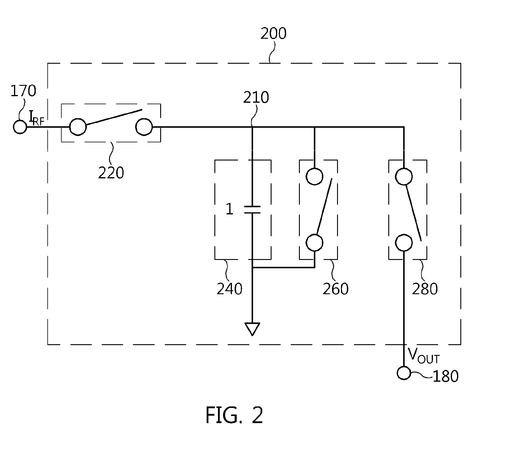
The present invention aims to improve the performance of a receiver by eliminating interference signals. It provides moving average filtering technology that can adjust the filter coefficients based on interference signals to be targeted for elimination. The filtering circuit is implemented using capacitors and switches, which offers economical efficiency, portability, and low power characteristics. The α-unit sampler allows for adjustment of sampling capacitance through control of switch operations. The invention thus offers an effective solution for eliminating interference signals and improving the performance of a receiver.

Problems solved by technology

However, it is very unrealistic to precisely control the value of an inductor reproduced by an analog filter to the value required by the frequency characteristics of the filter.
However, a conventional spatial moving average filter having N consecutive weights of a constant value is problematic in that null frequencies can be located only at frequencies (n·fs / D) corresponding to n times a value obtained by dividing a sampling frequency fs by a decimation ratio D, and in that it is difficult to eliminate some interference signals even when adjusting the length of a moving average, in order to use the null frequencies to eliminate interference signals.

Method used


Image

  • Moving average filter based on charge sampling and moving average filtering method using the same
  • Moving average filter based on charge sampling and moving average filtering method using the same
  • Moving average filter based on charge sampling and moving average filtering method using the same

Examples


Embodiment Construction

[0032]The present invention will be described in detail below with reference to the accompanying drawings. In the following description, redundant descriptions and detailed descriptions of known functions and elements that may unnecessarily make the gist of the present invention obscure will be omitted. Embodiments of the present invention are provided to fully describe the present invention to those having ordinary knowledge in the art to which the present invention pertains. Accordingly, in the drawings, the shapes and sizes of elements may be exaggerated for the sake of clearer description.

[0033]Hereinafter, the configuration and operation of a moving average filter based on charge sampling according to the present invention will be described with reference to the attached drawings.

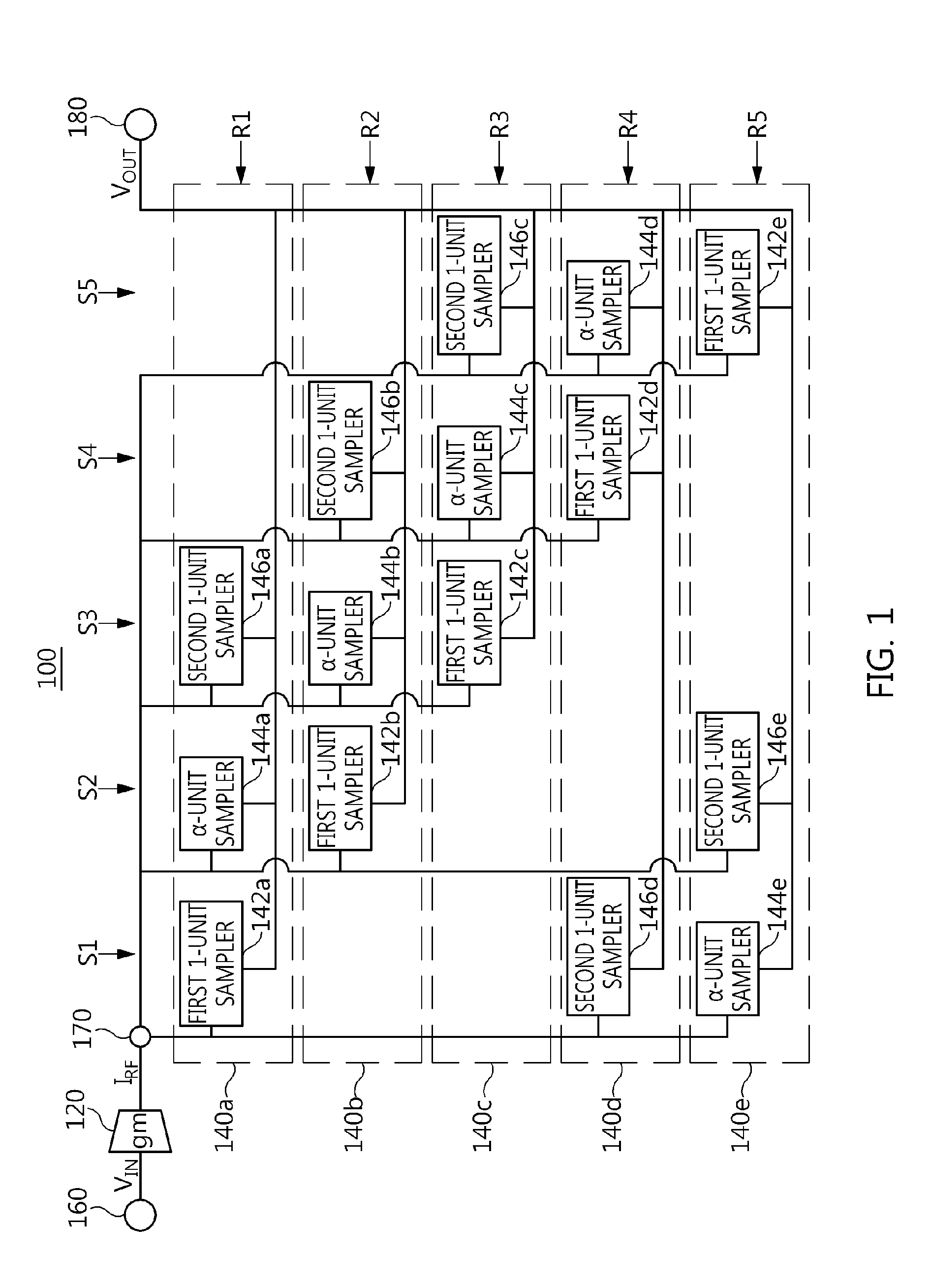
[0034]FIG. 1 is a diagram showing the configuration of a moving average filter based on charge sampling according to the present invention.

[0035]Referring to FIG. 1, a moving average filter 100 based o...


PUM


Abstract

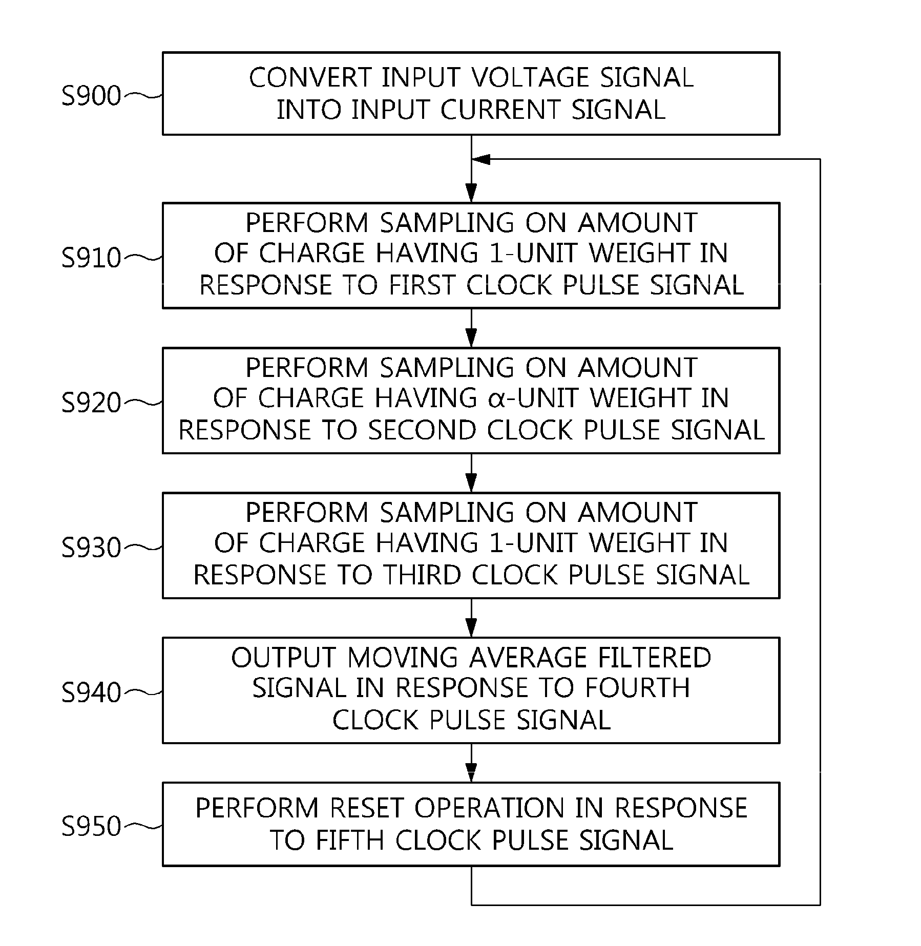
The present invention relates to a movement average filter based on charge sampling and a moving average filtering method using the same. The moving average filter includes a voltage-current converter and a first sampling unit. The voltage-current converter converts an input voltage signal into an input current signal and outputs the input current signal. The first sampling unit includes a first 1-unit sampler, an α-unit sampler, and a second 1-unit sampler connected in parallel between an output terminal of the voltage-current converter and a filtered signal output terminal, wherein each of the first 1-unit sampler, the α-unit sampler, and the second 1-unit sampler has a sampling capacitor bank for performing charge sampling. A ratio of sampling capacitances of sampling capacitor banks of the first 1-unit sampler, the α-unit sampler, and the second 1-unit sampler is 1:α:1, wherein a is adjusted to have a value between 1 and 2.

Description

CROSS REFERENCE TO RELATED APPLICATION[0001]This application claims the benefit of Korean Patent Application No. 10-2012-0057414, filed on May 30, 2012, which is hereby incorporated by reference in its entirety into this application.BACKGROUND OF THE INVENTION[0002]1. Technical Field[0003]The present invention relates generally to a movement average filter based on charge sampling and a moving average filtering method using the moving average filter and, more particularly, to a movement average filter based on charge sampling and a moving average filtering method using the moving average filter, which can select the characteristics of a filter having a required form by varying the filter coefficients of the moving average filter based on charge sampling, thus efficiently eliminating interference signals such as interference waves.[0004]2. Description of the Related Art[0005]Discrete-time Radio Frequency (RF) technology is a field that has newly dawned in radio digital communications...

Claims


Application Information

Patent Timeline
IPC IPC(8): H03K5/00
CPCH03K5/00H03H17/00
Inventor PARK, JANG-HYUNCHOI, SEONG-HOONJANG, IN-SUKIM, CHANG-BEOMCHO, YONG-HOSHIN, SOO-HWANKWEON, SOON-JAEYOO, HYUNG-JOUN
Owner ELECTRONICS & TELECOMM RES INST
Learn More